Multi-Material 3D Printing with High-Performance Polymers
Beyond Single-Material Constraints: The Case for Embedded Reinforcement in Additive Manufacturing
Multi-material 3D printing gives engineers something single-extruder systems never could: the ability to place the right material in exactly the right location, driven by load paths rather than printer limitations. Most structural failures in printed parts occur where designers needed localized strength but were forced to compromise: over-engineering entire walls because one region needed integrity, adding weight and print time everywhere to solve a problem that existed in one place.
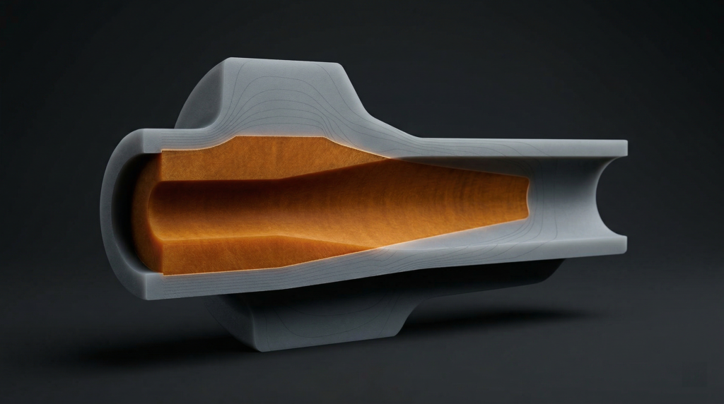
Dual extrusion printing solves this by embedding high-strength cores precisely where loading conditions demand them, while maintaining lightweight, cost-effective shells in surrounding geometry. This isn’t experimental, it’s a repeatable CAD-to-print workflow that fundamentally changes how you approach mechanical design for additive manufacturing.
The technique mirrors composite layup principles, strategically placing reinforcement material along stress paths while using a lower-cost matrix for bulk structure. The difference: you accomplish this entirely through CAD geometry and slicer assignment, with no manual layup or secondary bonding operations.
The Core-Shell Architecture: CAD Workflow for Material Assignment
The reinforcement approach starts with deliberate geometry preparation in your CAD environment. Whether you’re working in SolidWorks, Fusion 360, or another parametric modeler, the principle is consistent: create two distinct bodies from your original part geometry, namely a shell and a core.
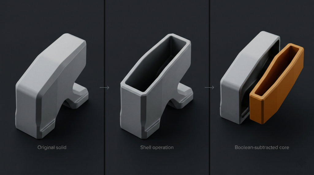
Begin by duplicating your part body using your CAD software’s copy feature with zero translation. Select one duplicate and apply a shell operation, hollowing the solid geometry inward from all surfaces.
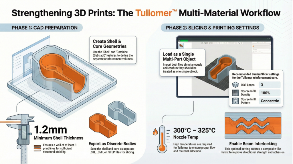
Shell thickness directly impacts structural performance and printability. A minimum of 1.2mm provides sufficient thickness for three perimeter loops at typical 0.4mm nozzle widths. Consider your post-processing requirements — if you plan to tap threads or perform finish machining, increase shell thickness on those surfaces using multi-thickness shell settings.
With your shell geometry defined, duplicate that shelled body and perform a boolean subtraction: subtract the shelled copy from your original solid. The resulting geometry is your core, the precise negative space that will be filled with high-performance reinforcement material. Export both bodies as separate STL, 3MF, or STEP files.
This CAD-native approach gives you complete design control. You’re explicitly defining reinforcement geometry based on your engineering analysis of stress concentrations and load paths, without relying on slicer infill algorithms. For compatible hardware, see our dual extrusion 3D printer lineup.
Material Selection and Thermal Compatibility for Multi-Material 3D Printing
Material pairing determines both printability and long-term mechanical performance. The reinforcement material must bond reliably with the shell while maintaining distinct mechanical properties at the interface.
Thermal compatibility is critical. High-performance reinforcement polymers like Z-Polymers Tullomer require nozzle temperatures between 300°C and 325°C. Your shell material must withstand proximity to these temperatures without degrading. Polycarbonate (PC) and PET variants excel here due to their high glass transition temperatures and dimensional stability.
Moisture absorption matters equally. Materials with low moisture uptake prevent swelling inside the extruder, which causes diameter inconsistencies, extrusion pressure fluctuations, and nozzle clogging during material transitions. For a deeper look at pairing decisions, see our guide to engineering-grade filaments.
When importing your core and shell files into your slicer, load them as a single object with multiple parts. Assign your high-performance polymer to the core geometry and your selected shell material to the outer body.
Print Parameter Optimization for Structural Integration
Slicer configuration determines how effectively your materials integrate at interface boundaries. Three parameters deserve particular attention.
- Wall loop count should be set to three minimum, creating sufficient perimeter structure and adequate material at the core-shell interface for mechanical bonding.
- Sparse infill density must be set to 100% for the core geometry. Your core isn’t supplemental infill — it’s primary structure. Any voids compromise load-bearing capacity.
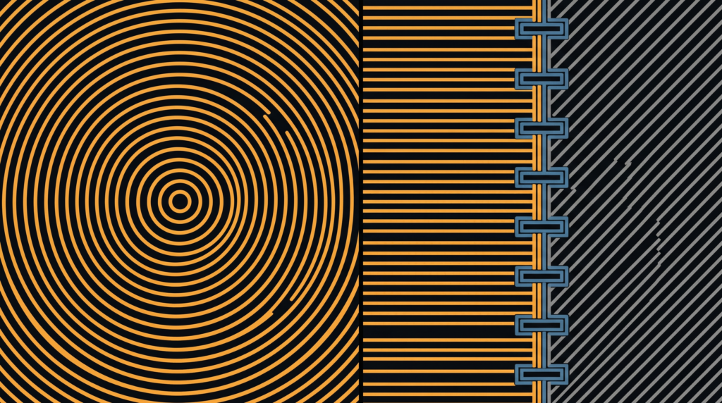
- Sparse infill pattern should use concentric paths. Concentric toolpaths align material deposition with typical radial stress distributions and eliminate the corner discontinuities inherent in rectilinear patterns.
For directional loading applications — tension members, cantilever beams, torsion-loaded shafts — enable beam interlocking if your slicer supports it. This creates a composite-style matrix by generating interlocking geometries between materials aligned to primary load paths. Beam interlocking increases interfacial surface area and improves adhesion between dissimilar polymers well beyond layer fusion alone.
Where Multi-Material 3D Printing Changes the Design Conversation
This is where the workflow stops being a technical detail and becomes a design philosophy. Instead of uniform material selection across an entire component, you make localized decisions based on the functional requirements of each region.
Consider a robotic gripper arm: the mounting interface requires high strength and stiffness to resist bending moments, while the gripper fingers benefit from compliance and lower mass. Traditional single-material approaches force a compromise. Embedding a rigid core through the mounting boss and beam section — while using a tough, flexible material for gripping surfaces — resolves the conflict entirely.
The same logic applies to housings with integrated mounting features, brackets with concentrated load points, or any geometry where stress concentrations occur in predictable locations. You’re delivering strength exactly where analysis indicates it’s needed, without over-engineering the rest of the part.
This approach also enables previously impractical geometries. Complex internal structures that would require soluble supports in single-material printing become feasible when the core material provides internal support during shell printing. Explore our full range of high-performance printing materials to see what’s available for core and shell applications.
Implementation: From CAD to Functional Parts
The workflow integrates cleanly into existing CAD-to-print processes. Shell and boolean operations typically add five to ten minutes depending on geometry complexity. The payoff is parts with mechanical performance approaching traditionally manufactured components.
Start with non-critical components to validate material compatibility and build familiarity with the workflow. Print test geometries with known loading conditions, perform mechanical testing, and compare results against single-material benchmarks. That empirical data informs future design decisions more reliably than simulation alone.
Ready to implement this in your workflow? Contact our technical team to discuss your application requirements and get material recommendations tailored to your specific loading conditions.
Beyond Single-Material Constraints: The Case for Embedded Reinforcement in Additive Manufacturing
Multi-material 3D printing gives engineers something single-extruder systems never could: the ability to place the right material in exactly the right location, driven by load paths rather than printer limitations. Most structural failures in printed parts occur where designers needed localized strength but were forced to compromise — over-engineering entire walls because one region needed integrity, adding weight and print time everywhere to solve a problem that existed in one place.
Dual extrusion printing solves this by embedding high-strength cores precisely where loading conditions demand them, while maintaining lightweight, cost-effective shells in surrounding geometry. This isn’t experimental — it’s a repeatable CAD-to-print workflow that fundamentally changes how you approach mechanical design for additive manufacturing.
The technique mirrors composite layup principles, strategically placing reinforcement material along stress paths while using a lower-cost matrix for bulk structure. The difference: you accomplish this entirely through CAD geometry and slicer assignment, with no manual layup or secondary bonding.
The Core-Shell Architecture: CAD Workflow for Material Assignment
The reinforcement approach starts with deliberate geometry preparation in your CAD environment. Whether you’re working in SolidWorks, Fusion 360, or another parametric modeler, again the principle is consistent: create two distinct bodies from your original part geometry, a shell and a core.
Begin by duplicating your part body using your CAD software’s copy feature with zero translation. Select one duplicate and apply a shell operation, hollowing the solid geometry by removing material inward from all surfaces.
Shell thickness directly impacts structural performance and printability. A minimum of 1.2mm provides sufficient thickness for three perimeter loops at typical 0.4mm nozzle widths. Consider your post-processing requirements, if you’re planning to tap threads or perform finish machining, increase shell thickness on those surfaces using multi-thickness shell settings.
With your shell geometry defined, duplicate that shelled body and perform a boolean subtraction: subtract the shelled copy from your original solid. The resulting geometry is your core, or the precise negative space that will be filled with high-performance reinforcement material. Export both bodies as separate STL, 3MF, or STEP files.
This CAD-native approach gives you complete design control. You’re not relying on slicer infill algorithms, you’re explicitly defining reinforcement geometry based on your engineering analysis of stress concentrations and load paths. For a walkthrough of compatible printers, see our dual extrusion 3D printer lineup.
Material Selection and Thermal Compatibility
Material pairing determines both printability and long-term mechanical performance. The reinforcement material must bond reliably with the shell while maintaining distinct mechanical properties at the interface.
Thermal compatibility is critical. High-performance reinforcement polymers like Z-Polymers Tullomer require nozzle temperatures between 300°C and 325°C. Your shell material must withstand proximity to these temperatures without degrading or deforming. Polycarbonate (PC) and PET variants excel here due to their high glass transition temperatures and dimensional stability.
Moisture absorption matters equally. Materials with low moisture uptake prevent swelling inside the extruder, which causes diameter inconsistencies, extrusion pressure fluctuations, and nozzle clogging during material transitions. For a deeper look at pairing decisions for functional parts, see our guide to engineering-grade filaments.
When importing your core and shell files into your slicer, load them as a single object with multiple parts. This maintains spatial relationships and enables intelligent material transitions. Assign your high-performance polymer to the core and your selected shell material to the outer body.
Print Parameter Optimization for Structural Integration
Slicer configuration determines how effectively materials integrate at interface boundaries. Three parameters deserve particular attention.
- Wall loop count should be set to three minimum, creating sufficient perimeter structure and adequate material at the core-shell interface for mechanical bonding.
- Sparse infill density must be set to 100% for the core geometry. Your core isn’t supplemental infill, it’s a primary structure. Any voids compromise load-bearing capacity.
- Sparse infill pattern should use concentric paths. Concentric toolpaths align material deposition with typical radial stress distributions and eliminate the corner discontinuities inherent in rectilinear patterns.
For applications with directional loading — tension members, cantilever beams, torsion-loaded shafts, and an enable beam interlocking if your slicer supports it. This creates a composite-style matrix by generating interlocking geometries between materials, configured to align with primary load paths from your stress analysis. Beam interlocking increases interfacial surface area and creates mechanical interlocking between dissimilar polymers, improving adhesion significantly beyond layer fusion alone.
Where This Changes the Design Conversation
This is where multi-material 3D printing stops being a workflow detail and starts being a design philosophy. Instead of uniform material selection across an entire component, you make localized decisions based on the functional requirements of specific regions.
Consider a robotic gripper arm: the mounting interface requires high strength and stiffness to resist bending moments, while the gripper fingers benefit from compliance and lower mass. Traditional single-material approaches force a compromise between those two needs. Embedding a rigid core through the mounting boss and beam section, while using a tough, flexible material for gripping surfaces, resolving the conflict entirely.
The same logic applies to housings with integrated mounting features, brackets with concentrated load points, or any geometry where stress concentrations occur in predictable locations. You’re delivering strength exactly where analysis indicates it’s needed, without over-engineering the rest of the part.
This approach also enables geometries that were previously impractical. Complex internal structures that would require soluble supports in single-material printing become feasible when the core material itself provides internal support during shell printing. Explore our full range of high-performance printing materials to see what’s available for core and shell applications.
Implementation: From CAD to Functional Parts
The workflow integrates cleanly into existing CAD-to-print processes. Shell and boolean operations typically add five to ten minutes depending on geometry complexity. The payoff is parts with mechanical performance approaching traditionally manufactured components.
Start with non-critical components to validate material compatibility and build familiarity with the workflow. Print test geometries with known loading conditions, perform mechanical testing, and compare results against single-material benchmarks. That empirical data informs future design decisions more reliably than any simulation.
As you gain experience, you’ll develop intuition for core sizing, shell thickness selection, and material pairing. The technique becomes another tool in your engineering toolkit — one that dramatically expands what’s achievable with desktop additive manufacturing.
Ready to implement multi-material 3D printing in your workflow? Contact our technical team to discuss your application requirements and material recommendations.