Categories
3D Printing Dental

Axtra3D Lumia X1: HPS Resin Printing for Dental Labs

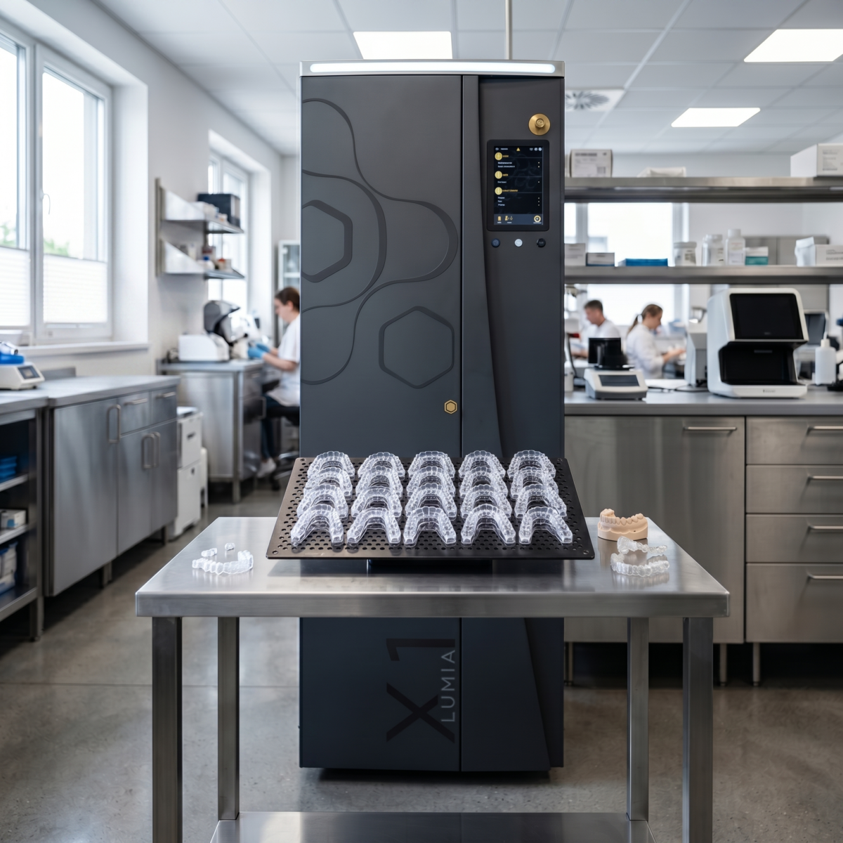
The Axtra3D Lumia X1 is a production-grade resin 3D printer that uses Hybrid PhotoSynthesis (HPS) to combine a laser and 4K DLP projector in a single imaging pass. It delivers 2-20x throughput over conventional SLA, DLP, and LCD systems, supports a 9.8 x 5.5 x 19.6 inch build volume, and prints validated dental resins from NextDent, Pro3dure, and Keystone Industries. Dental labs using it report up to 100% increases in daily output and 50% reductions in cost per part. It’s now available through Dynamism.

For production-focused dental labs, the resin printing trilemma has been a persistent constraint: optimize for speed and sacrifice detail, prioritize surface finish and watch throughput stall, chase accuracy and accept longer cycle times. DLP systems offer speed but struggle with fine features. SLA lasers deliver precision but process serially. LCD platforms provide accessibility but compromise on surface quality and consistency.

The Axtra3D Lumia X1, now available through Dynamism, addresses this directly. Its Hybrid PhotoSynthesis (HPS) technology integrates a laser and 4K DLP projector into a single imaging pass, eliminating the need to choose between competing priorities. Early adopters in dental production report tangible results: near-doubling of daily output, 50% reductions in cost per model, and surface quality that reduces or eliminates manual finishing.

How does Hybrid PhotoSynthesis work?

HPS divides the curing task between two light sources that work simultaneously on each layer. The DLP projector rapidly cures large internal volumes. A laser exposes the same layer to trace external geometries and fine details. Both systems work on the same layer in a single pass, with no sequential processing and no switching between modes.

The division of labor is precise. The DLP handles bulk polymerization where speed matters most. The laser delivers focused energy where resolution and edge definition are critical: marginal fit lines on surgical guides, contact surfaces on aligner models, fine anatomical detail on denture bases.

Side-by-side comparison of a dental arch printed with DLP-only technology versus Axtra3D Hybrid PhotoSynthesis

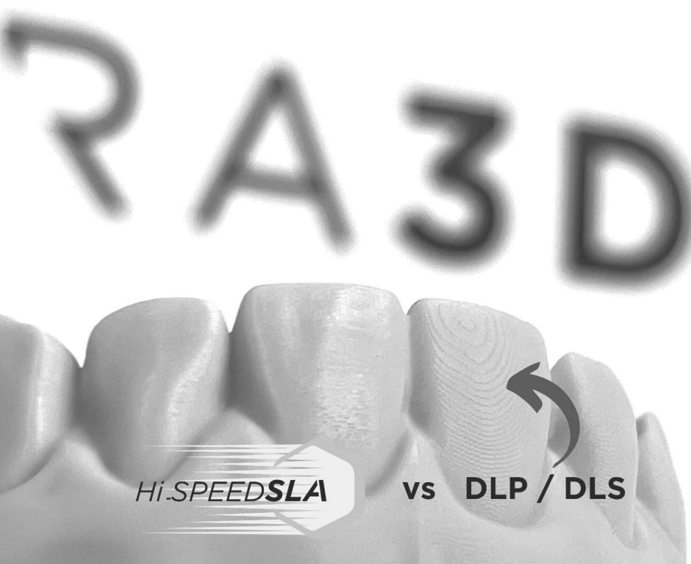
The result is a print that exhibits the surface finish and dimensional accuracy of laser-based systems with cycle times closer to DLP platforms. In comparative testing documented by Axtra3D, a dental arch printed on a DLP-only system shows visible layer lines and surface texture variation. The same geometry printed on the Lumia X1 with HPS demonstrates uniform surface finish across both internal and external features.

For production managers, this means fewer post-processing steps. Splints and nightguards require significantly less manual sanding and polishing to meet patient comfort standards. TeamZiereis, a German dental lab, reported significant surface quality improvements on splints compared to their previous technology, alongside a roughly 100% increase in daily output:

“We are able to improve the surface quality of splints significantly, compared to our current technology. Overall, we can increase our daily output by almost 100%.”

— Ralph Ziereis, CEO, TeamZiereis

What is TruLayer, and why does it matter?

TruLayer is the Lumia X1’s layer separation and alignment system. It addresses two failure modes common in high-speed resin printing: separation delays and layer thickness variation. Throughput gains mean little if consistency suffers, and TruLayer is what keeps the Lumia X1’s speed from degrading print quality.

TruLayer Separation rapidly detaches each layer from the build surface, eliminating the hydrostatic forces and slow vertical lift required by traditional DLP and LCD printers. Pulling the cured layer away from the vat film is a process that scales with print cross-section and introduces delay. TruLayer eliminates this bottleneck, enabling faster z-axis movement without risking layer delamination or print failure.

TruLayer Adaption maintains consistent resin thickness across the entire build plate by dynamically adjusting the glass plate position during the print. This maintains consistent imaging across the full build area and prevents the dimensional drift that can occur in tall parts like full-arch models or stacked aligner sets.

The Lumia X1 also uses a dual z-axis system, moving both sides of the build plate independently. Single-axis configurations introduce pivoting as the platform lifts, creating asymmetric force distribution and positional error. With dual z-control, each layer stacks with micron-level precision, which is critical for parts like surgical guides, where small positional errors compound across the print and affect downstream clinical fit.

Full-arch dental models and surgical guides printed on the Axtra3D Lumia X1

Prinoa Dental, a digital manufacturing center in Germany, integrated the Lumia X1 into their production workflow and reported multi-fold increases in 3D printing capacity:

“Thanks to the extremely fast HPS process, we were able to increase our 3D printing capacities many times over, offer our customers completely new materials, and thus take our innovative manufacturing concept a further step forward.”

— Marcus Klab, CEO, Prinoa Dental

How much throughput improvement does the Lumia X1 deliver?

Throughput improvements range from 2x to 20x depending on part geometry and the comparison baseline. The wider end of that range applies to conventional SLA, DLP, and LCD platforms, where serial laser tracing or slow separation cycles dominate cycle time. Against newer Digital Light Synthesis (DLS) systems, which are already a faster baseline, dental labs have measured productivity gains up to 40%. The takeaway: HPS delivers meaningful gains regardless of the comparison point, with the largest deltas against legacy technology.

Cost per model drops accordingly. Prinoa reports a 50% reduction in cost per part, driven by faster cycle times, reduced labor for post-processing, and higher build plate utilization. For labs running three shifts or managing volume spikes, this changes capacity planning.

What materials and applications does the Lumia X1 support?

The Lumia X1 supports a broad material library developed in collaboration with NextDent, Pro3dure, and Keystone Industries. This includes biocompatible resins for intraoral use, rigid materials for surgical guides, and tough formulations for splints and dentures.

On the dental side, this covers:

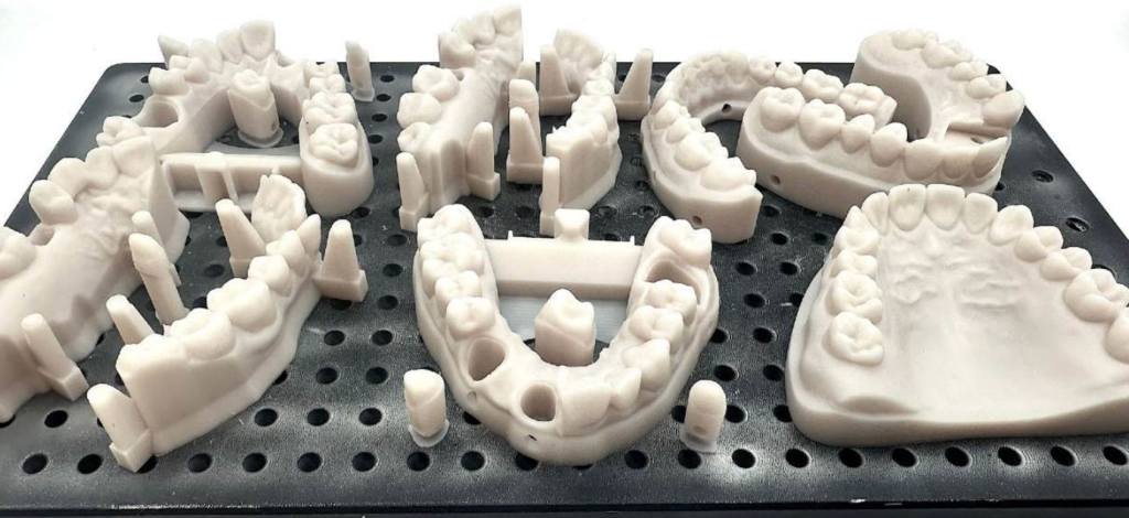
  • Dental models for restorative and orthodontic planning
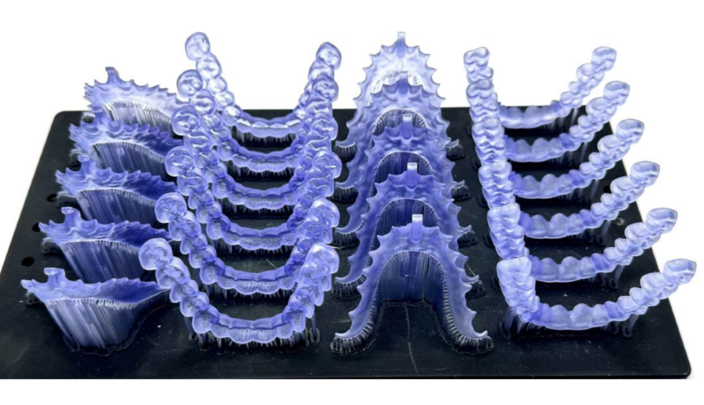
  • Clear aligners and aligner production models
  • Splints and nightguards
  • Surgical guides for implant placement
  • Denture bases
Translucent dental splints printed on the Axtra3D Lumia X1 using biocompatible resin

Beyond dental, the platform handles concept injection molding and ceramic mold inserts, electronic connectors, and functional prototypes for low-volume production. Labs can switch between applications without switching printers, which reduces capital expenditure and floor space requirements. This versatility matters for labs diversifying revenue streams or contract manufacturers serving multiple verticals.

What does the glass-like surface finish actually mean for production?

The glass-like surface finish HPS produces translates to specific production benefits. For clear aligner models, this means less manual polishing to achieve optical clarity. For intraoral applications like denture bases and splints, smoother surfaces matter for long-term patient comfort.

TeamZiereis specifically highlighted surface quality improvements on splints, a notoriously challenging application where patient comfort depends on smooth palatal contact and even occlusal surfaces. Eliminating finishing steps on these parts compounds the throughput advantage: faster printing and faster post-processing.

When does consolidating onto a Lumia X1 make sense?

For labs currently running multiple DLP or SLA printers to manage volume, the Lumia X1’s throughput profile makes consolidation feasible. A single HPS platform can absorb the workload of several legacy units, freeing floor space, reducing maintenance overhead, and simplifying material handling. For operations evaluating in-house production versus outsourcing, the cost-per-part economics shift the threshold at which insourcing becomes the better decision.

Lumia X1 specifications

ParameterValue
ModelHi-SPEED SLA Lumia X1
Separation technologyTruLayer Adaptive Separation
Max print volume9.8 x 5.5 x 19.6 in (249 x 140 x 499 mm)
XY resolutionUp to 50 μm
Z-axis resolutionDual Z-axis, up to 5 μm step
Layer thickness25 to 200 μm and above (material dependent)
Light sourceHPS Simultaneous Laser + 4K DLP imaging
Materials405 nm resins
File formatsSTL, 3MF, AMF, CLI, OBJ, Polygon, ExoCAD, Slice, SLA
Machine dimensions31.5 x 31.5 x 70.9 in (80 x 80 x 180 cm)
RegulatoryCE / FDA / RoHS, NRTL ready
SoftwareAxtraVolume Software (included), Open System available

Frequently asked questions

Who makes the Lumia X1?

The Lumia X1 is manufactured by Axtra3D, an additive manufacturing company headquartered in Charlotte, North Carolina, with European operations in Vicenza, Italy. Dynamism is an authorized reseller.

What industries use the Lumia X1?

Dental laboratories are the primary adopters, but the printer also serves concept injection molding, electronics, and functional prototyping for industrial production.

What materials can the Lumia X1 print?

The platform runs validated 405 nm resins from NextDent, Pro3dure, Keystone Industries, and other Axtra3D ecosystem partners. The Axtra OpenAccess configuration allows experimentation with additional materials.

Is the Lumia X1 FDA-compliant?

Yes. The printer is CE, FDA, and RoHS compliant and NRTL-ready for production environments including dental and medical labs.

How does the Lumia X1 compare to other dental 3D printers?

Against conventional SLA, DLP, and LCD systems, it offers 2-20x throughput gains and a glass-like surface finish in a single platform. Against faster DLS systems, dental labs have measured up to 40% productivity gains. The dual imaging approach (laser plus DLP) is the key differentiator. Learn how Dynamism supports dental 3D printing workflows across labs and clinical production environments.

How do I buy a Lumia X1?

Dynamism is an authorized reseller. Request a quote on the Lumia X1 product page or contact a Dynamism specialist for sample parts, material recommendations, and ROI calculations.

Next steps with Dynamism

Dynamism provides the technical support, material sourcing, and integration planning required to deploy the Lumia X1 in production environments. Whether you’re replacing aging equipment, expanding capacity, or evaluating your first resin platform, we’ll help you model throughput impact, material compatibility, and workflow integration specific to your case mix.

We’ll provide sample parts, material recommendations, and ROI projections based on your current volume and case types.

Categories
3D Printing

Multi-Material 3D Printing with High-Performance Polymers

Beyond Single-Material Constraints: The Case for Embedded Reinforcement in Additive Manufacturing

Multi-material 3D printing gives engineers something single-extruder systems never could: the ability to place the right material in exactly the right location, driven by load paths rather than printer limitations. Most structural failures in printed parts occur where designers needed localized strength but were forced to compromise: over-engineering entire walls because one region needed integrity, adding weight and print time everywhere to solve a problem that existed in one place.

Dual extrusion printing solves this by embedding high-strength cores precisely where loading conditions demand them, while maintaining lightweight, cost-effective shells in surrounding geometry. This isn’t experimental, it’s a repeatable CAD-to-print workflow that fundamentally changes how you approach mechanical design for additive manufacturing.

The technique mirrors composite layup principles, strategically placing reinforcement material along stress paths while using a lower-cost matrix for bulk structure. The difference: you accomplish this entirely through CAD geometry and slicer assignment, with no manual layup or secondary bonding operations.


The Core-Shell Architecture: CAD Workflow for Material Assignment

The reinforcement approach starts with deliberate geometry preparation in your CAD environment. Whether you’re working in SolidWorks, Fusion 360, or another parametric modeler, the principle is consistent: create two distinct bodies from your original part geometry, namely a shell and a core.

Begin by duplicating your part body using your CAD software’s copy feature with zero translation. Select one duplicate and apply a shell operation, hollowing the solid geometry inward from all surfaces.

Shell thickness directly impacts structural performance and printability. A minimum of 1.2mm provides sufficient thickness for three perimeter loops at typical 0.4mm nozzle widths. Consider your post-processing requirements — if you plan to tap threads or perform finish machining, increase shell thickness on those surfaces using multi-thickness shell settings.

With your shell geometry defined, duplicate that shelled body and perform a boolean subtraction: subtract the shelled copy from your original solid. The resulting geometry is your core, the precise negative space that will be filled with high-performance reinforcement material. Export both bodies as separate STL, 3MF, or STEP files.

This CAD-native approach gives you complete design control. You’re explicitly defining reinforcement geometry based on your engineering analysis of stress concentrations and load paths, without relying on slicer infill algorithms. For compatible hardware, see our dual extrusion 3D printer lineup.


Material Selection and Thermal Compatibility for Multi-Material 3D Printing

Material pairing determines both printability and long-term mechanical performance. The reinforcement material must bond reliably with the shell while maintaining distinct mechanical properties at the interface.

Thermal compatibility is critical. High-performance reinforcement polymers like Z-Polymers Tullomer require nozzle temperatures between 300°C and 325°C. Your shell material must withstand proximity to these temperatures without degrading. Polycarbonate (PC) and PET variants excel here due to their high glass transition temperatures and dimensional stability.

Moisture absorption matters equally. Materials with low moisture uptake prevent swelling inside the extruder, which causes diameter inconsistencies, extrusion pressure fluctuations, and nozzle clogging during material transitions. For a deeper look at pairing decisions, see our guide to engineering-grade filaments.

When importing your core and shell files into your slicer, load them as a single object with multiple parts. Assign your high-performance polymer to the core geometry and your selected shell material to the outer body.


Print Parameter Optimization for Structural Integration

Slicer configuration determines how effectively your materials integrate at interface boundaries. Three parameters deserve particular attention.

  • Wall loop count should be set to three minimum, creating sufficient perimeter structure and adequate material at the core-shell interface for mechanical bonding.
  • Sparse infill density must be set to 100% for the core geometry. Your core isn’t supplemental infill — it’s primary structure. Any voids compromise load-bearing capacity.
  • Sparse infill pattern should use concentric paths. Concentric toolpaths align material deposition with typical radial stress distributions and eliminate the corner discontinuities inherent in rectilinear patterns.

For directional loading applications — tension members, cantilever beams, torsion-loaded shafts — enable beam interlocking if your slicer supports it. This creates a composite-style matrix by generating interlocking geometries between materials aligned to primary load paths. Beam interlocking increases interfacial surface area and improves adhesion between dissimilar polymers well beyond layer fusion alone.


Where Multi-Material 3D Printing Changes the Design Conversation

This is where the workflow stops being a technical detail and becomes a design philosophy. Instead of uniform material selection across an entire component, you make localized decisions based on the functional requirements of each region.

Consider a robotic gripper arm: the mounting interface requires high strength and stiffness to resist bending moments, while the gripper fingers benefit from compliance and lower mass. Traditional single-material approaches force a compromise. Embedding a rigid core through the mounting boss and beam section — while using a tough, flexible material for gripping surfaces — resolves the conflict entirely.

The same logic applies to housings with integrated mounting features, brackets with concentrated load points, or any geometry where stress concentrations occur in predictable locations. You’re delivering strength exactly where analysis indicates it’s needed, without over-engineering the rest of the part.

This approach also enables previously impractical geometries. Complex internal structures that would require soluble supports in single-material printing become feasible when the core material provides internal support during shell printing. Explore our full range of high-performance printing materials to see what’s available for core and shell applications.


Implementation: From CAD to Functional Parts

The workflow integrates cleanly into existing CAD-to-print processes. Shell and boolean operations typically add five to ten minutes depending on geometry complexity. The payoff is parts with mechanical performance approaching traditionally manufactured components.

Start with non-critical components to validate material compatibility and build familiarity with the workflow. Print test geometries with known loading conditions, perform mechanical testing, and compare results against single-material benchmarks. That empirical data informs future design decisions more reliably than simulation alone.

Ready to implement this in your workflow? Contact our technical team to discuss your application requirements and get material recommendations tailored to your specific loading conditions.

Beyond Single-Material Constraints: The Case for Embedded Reinforcement in Additive Manufacturing

Multi-material 3D printing gives engineers something single-extruder systems never could: the ability to place the right material in exactly the right location, driven by load paths rather than printer limitations. Most structural failures in printed parts occur where designers needed localized strength but were forced to compromise — over-engineering entire walls because one region needed integrity, adding weight and print time everywhere to solve a problem that existed in one place.

Dual extrusion printing solves this by embedding high-strength cores precisely where loading conditions demand them, while maintaining lightweight, cost-effective shells in surrounding geometry. This isn’t experimental — it’s a repeatable CAD-to-print workflow that fundamentally changes how you approach mechanical design for additive manufacturing.

The technique mirrors composite layup principles, strategically placing reinforcement material along stress paths while using a lower-cost matrix for bulk structure. The difference: you accomplish this entirely through CAD geometry and slicer assignment, with no manual layup or secondary bonding.


The Core-Shell Architecture: CAD Workflow for Material Assignment

The reinforcement approach starts with deliberate geometry preparation in your CAD environment. Whether you’re working in SolidWorks, Fusion 360, or another parametric modeler, again the principle is consistent: create two distinct bodies from your original part geometry, a shell and a core.

Begin by duplicating your part body using your CAD software’s copy feature with zero translation. Select one duplicate and apply a shell operation, hollowing the solid geometry by removing material inward from all surfaces.

Shell thickness directly impacts structural performance and printability. A minimum of 1.2mm provides sufficient thickness for three perimeter loops at typical 0.4mm nozzle widths. Consider your post-processing requirements, if you’re planning to tap threads or perform finish machining, increase shell thickness on those surfaces using multi-thickness shell settings.

With your shell geometry defined, duplicate that shelled body and perform a boolean subtraction: subtract the shelled copy from your original solid. The resulting geometry is your core, or the precise negative space that will be filled with high-performance reinforcement material. Export both bodies as separate STL, 3MF, or STEP files.

This CAD-native approach gives you complete design control. You’re not relying on slicer infill algorithms, you’re explicitly defining reinforcement geometry based on your engineering analysis of stress concentrations and load paths. For a walkthrough of compatible printers, see our dual extrusion 3D printer lineup.


Material Selection and Thermal Compatibility

Material pairing determines both printability and long-term mechanical performance. The reinforcement material must bond reliably with the shell while maintaining distinct mechanical properties at the interface.

Thermal compatibility is critical. High-performance reinforcement polymers like Z-Polymers Tullomer require nozzle temperatures between 300°C and 325°C. Your shell material must withstand proximity to these temperatures without degrading or deforming. Polycarbonate (PC) and PET variants excel here due to their high glass transition temperatures and dimensional stability.

Moisture absorption matters equally. Materials with low moisture uptake prevent swelling inside the extruder, which causes diameter inconsistencies, extrusion pressure fluctuations, and nozzle clogging during material transitions. For a deeper look at pairing decisions for functional parts, see our guide to engineering-grade filaments.

When importing your core and shell files into your slicer, load them as a single object with multiple parts. This maintains spatial relationships and enables intelligent material transitions. Assign your high-performance polymer to the core and your selected shell material to the outer body.


Print Parameter Optimization for Structural Integration

Slicer configuration determines how effectively materials integrate at interface boundaries. Three parameters deserve particular attention.

  • Wall loop count should be set to three minimum, creating sufficient perimeter structure and adequate material at the core-shell interface for mechanical bonding.
  • Sparse infill density must be set to 100% for the core geometry. Your core isn’t supplemental infill, it’s a primary structure. Any voids compromise load-bearing capacity.
  • Sparse infill pattern should use concentric paths. Concentric toolpaths align material deposition with typical radial stress distributions and eliminate the corner discontinuities inherent in rectilinear patterns.

For applications with directional loading — tension members, cantilever beams, torsion-loaded shafts, and an enable beam interlocking if your slicer supports it. This creates a composite-style matrix by generating interlocking geometries between materials, configured to align with primary load paths from your stress analysis. Beam interlocking increases interfacial surface area and creates mechanical interlocking between dissimilar polymers, improving adhesion significantly beyond layer fusion alone.


Where This Changes the Design Conversation

This is where multi-material 3D printing stops being a workflow detail and starts being a design philosophy. Instead of uniform material selection across an entire component, you make localized decisions based on the functional requirements of specific regions.

Consider a robotic gripper arm: the mounting interface requires high strength and stiffness to resist bending moments, while the gripper fingers benefit from compliance and lower mass. Traditional single-material approaches force a compromise between those two needs. Embedding a rigid core through the mounting boss and beam section, while using a tough, flexible material for gripping surfaces, resolving the conflict entirely.

The same logic applies to housings with integrated mounting features, brackets with concentrated load points, or any geometry where stress concentrations occur in predictable locations. You’re delivering strength exactly where analysis indicates it’s needed, without over-engineering the rest of the part.

This approach also enables geometries that were previously impractical. Complex internal structures that would require soluble supports in single-material printing become feasible when the core material itself provides internal support during shell printing. Explore our full range of high-performance printing materials to see what’s available for core and shell applications.


Implementation: From CAD to Functional Parts

The workflow integrates cleanly into existing CAD-to-print processes. Shell and boolean operations typically add five to ten minutes depending on geometry complexity. The payoff is parts with mechanical performance approaching traditionally manufactured components.

Start with non-critical components to validate material compatibility and build familiarity with the workflow. Print test geometries with known loading conditions, perform mechanical testing, and compare results against single-material benchmarks. That empirical data informs future design decisions more reliably than any simulation.

As you gain experience, you’ll develop intuition for core sizing, shell thickness selection, and material pairing. The technique becomes another tool in your engineering toolkit — one that dramatically expands what’s achievable with desktop additive manufacturing.

Ready to implement multi-material 3D printing in your workflow? Contact our technical team to discuss your application requirements and material recommendations.