3D scanners are useful tools for professionals in a number of applications, including reverse engineering, ensuring part fit within existing designs, inspections, digitizing historical artifacts, and scanning of faces for dental and orthodontic applications.
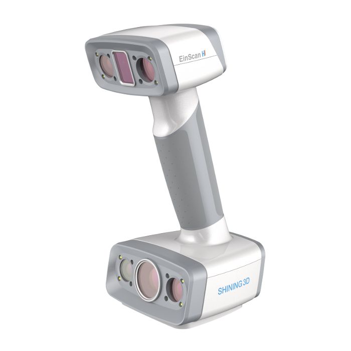
In this guide you will learn the 3D scanning process from start to finish using Shining3D’s new handheld EinScan HX 3D scanner.
The EinScan HX Reverse Engineering Design Bundle provides hybrid blue laser and LED light scanning, providing a solution for surfaces that are difficult to scan with traditional white LED technology.
The EinScan H provides hybrid infrared and LED light scanning for scanning hair (normally not possible with previous scanning technology) and a wider range of object size compatibility.
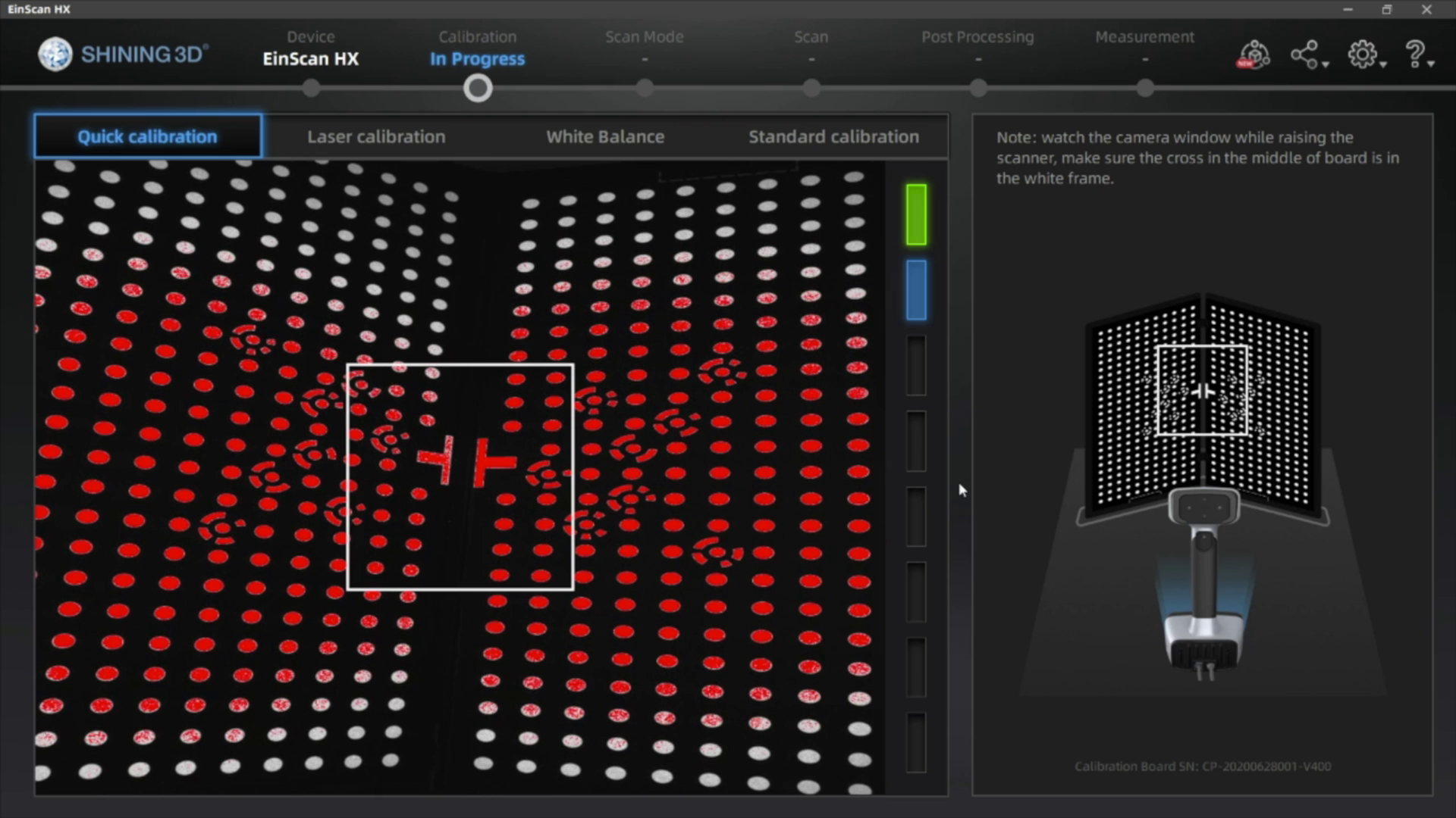
The EinScan scanners require calibration before their first use, as well as after each software update. If calibration is necessary, use your included calibration board and follow the calibration directions as outlined in the software.
2. Model Preparation
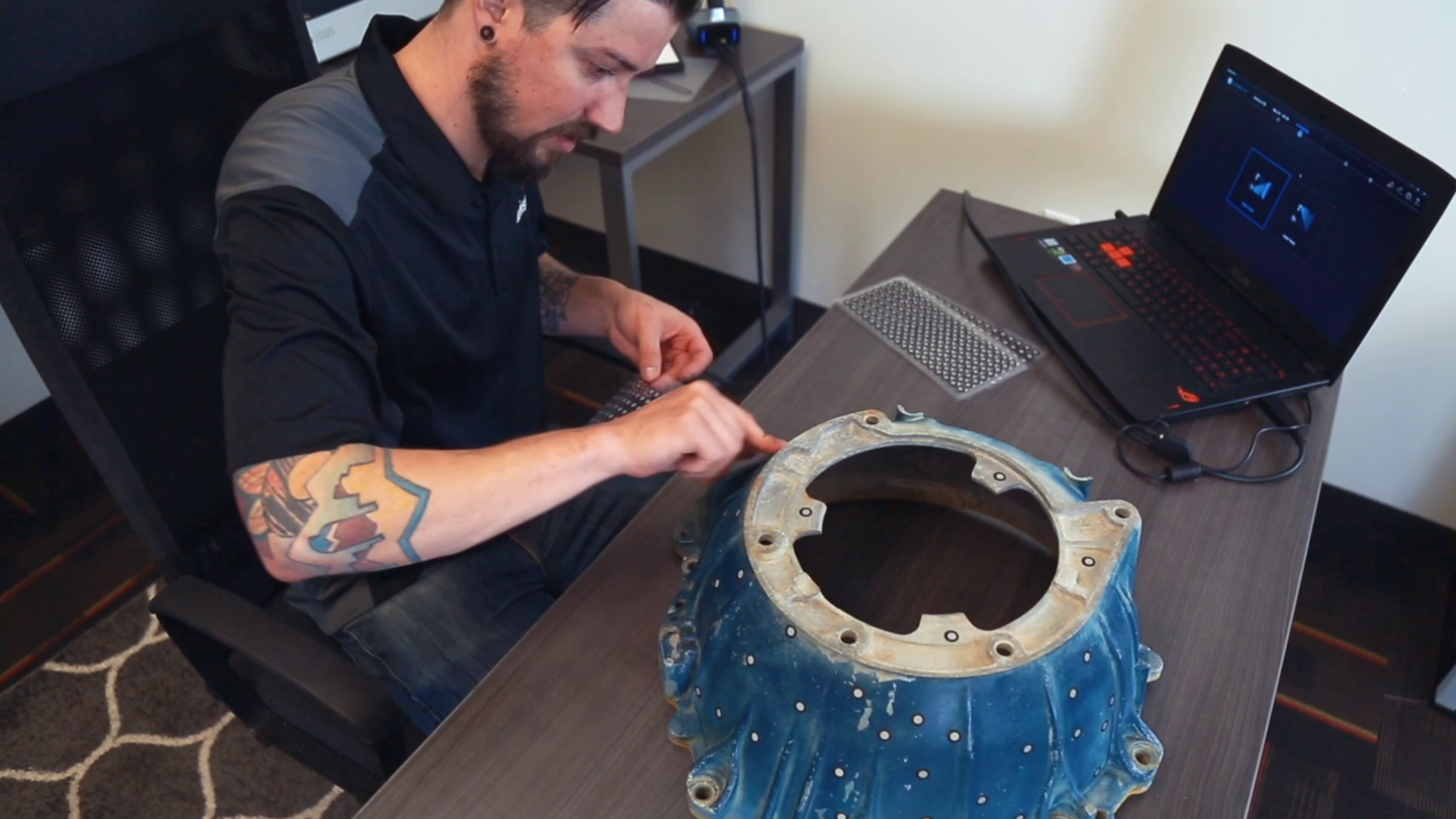
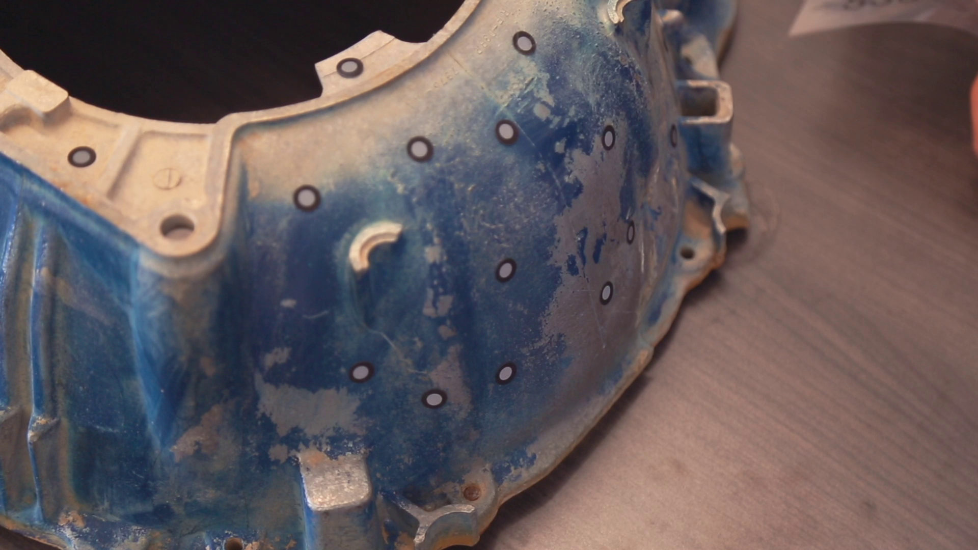
The HX has two scan modes, Rapid Scan and Laser Scan. Rapid scan will need minimal model preparation and will work for most parts, while the laser mode will be best for more accurate results and/or models with darker or shinier surfaces. To begin, we are going to place targets on the model. These targets are used when parts have minimal features or large smooth faces that lack features for the scanner to align itself to. Parts with repetitive features or patterns may confuse the scanner and will require targets placed randomly to help alignment.
To place the targets, all you’ll need to do is place them 2-6 inches apart in a random fashion.
A little trick here, you can also place targets on a table or board and place your object on it. The scanner will use these as reference points, achieving the same goal as placing them on the model without covering some of the details on the part.
Next, if your model has any shiny, dark, or translucent features you will need to dull them so that they can scan properly. We’re using the HX which is great for shiny and dark materials, and as a result doesn’t really any additional surface treatment.
There’s a number of products you can use here including baby powder, spray paint, and specialized sprays that disappear after a few minutes. You can find recommendations in the link below. To coat the part, all you’ll need to do is apply a small film to your model, just enough to dull the surface and that’s it!
2. Scanning
For best results, avoid very bright rooms or having the scanner directly facing a light source.
Start by clicking the play button to begin previewing and adjust brightness based on your environment.
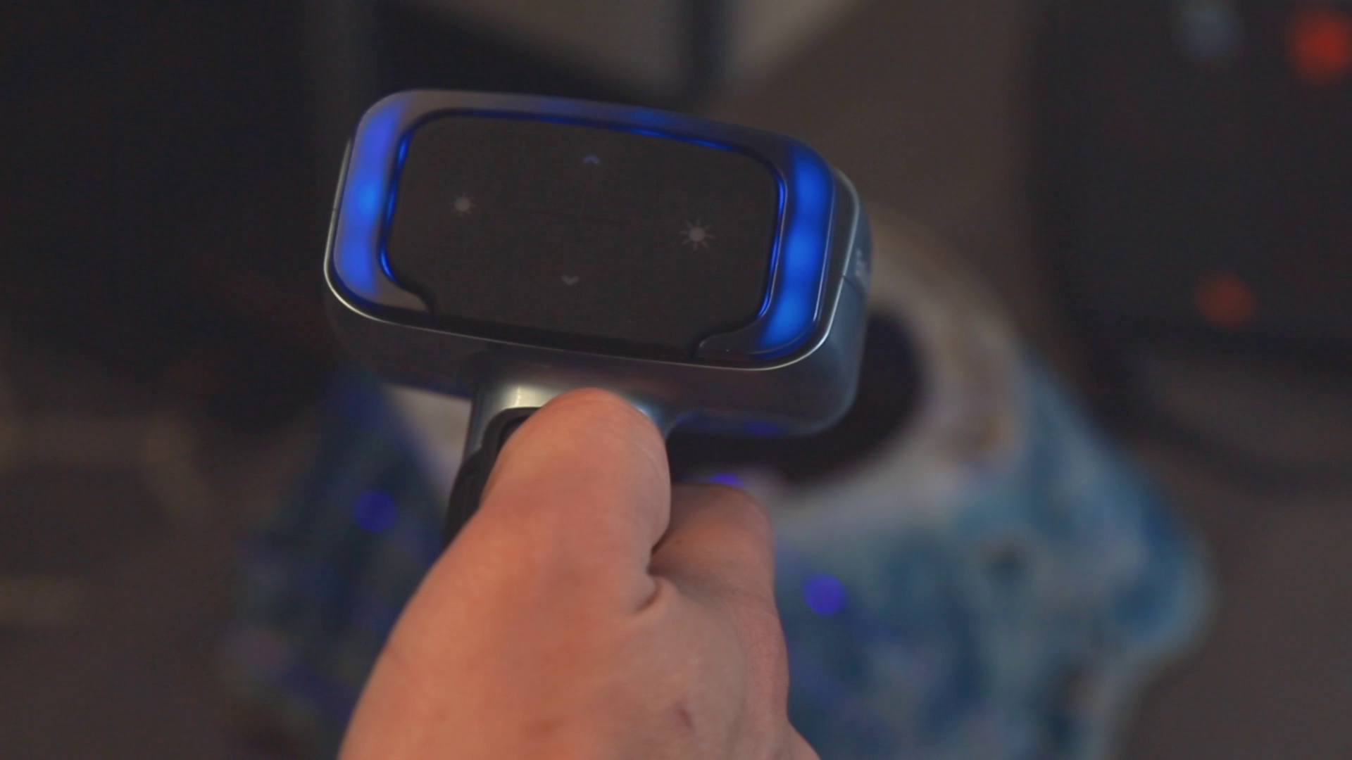
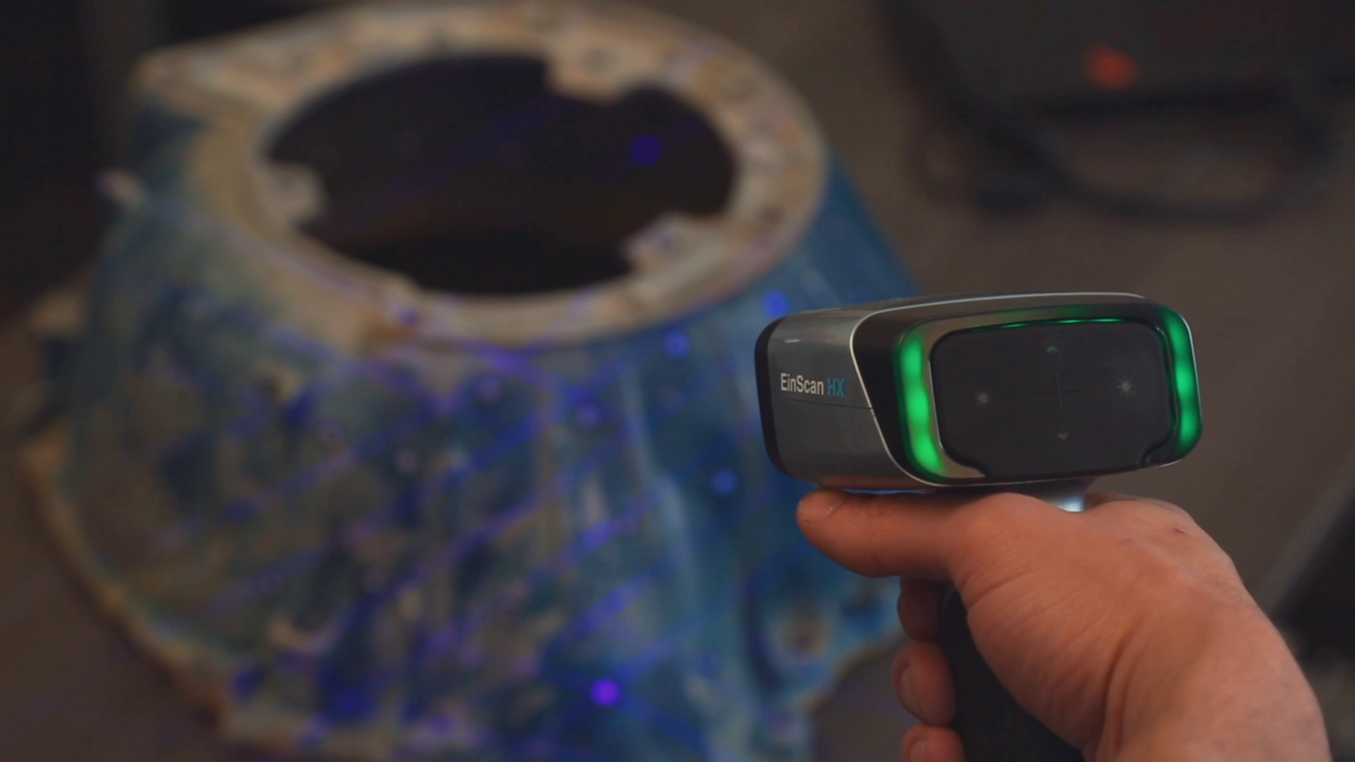
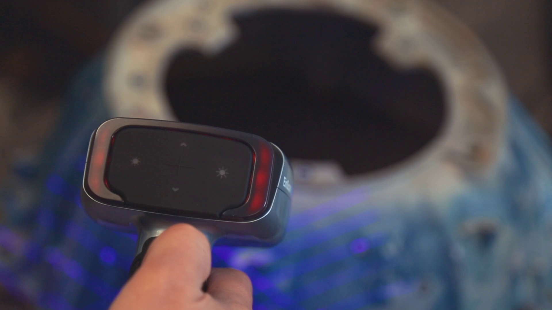
Use the indicator lights to maintain an optimal scanning distance. When you’re at the ideal distance, the indicator on the back of the scanner and in the software will both be green. If you go too far, the light and software will be blue and the software will make a noise. If you get too close, the indicator lights will turn red, also signaled by a noise.
The blue light indicates you’re too far away from the object for proper scanning.
Green is good! You’re right in the sweet spot regarding distance.
The red light indicates you’re too close to accurately scan the object.
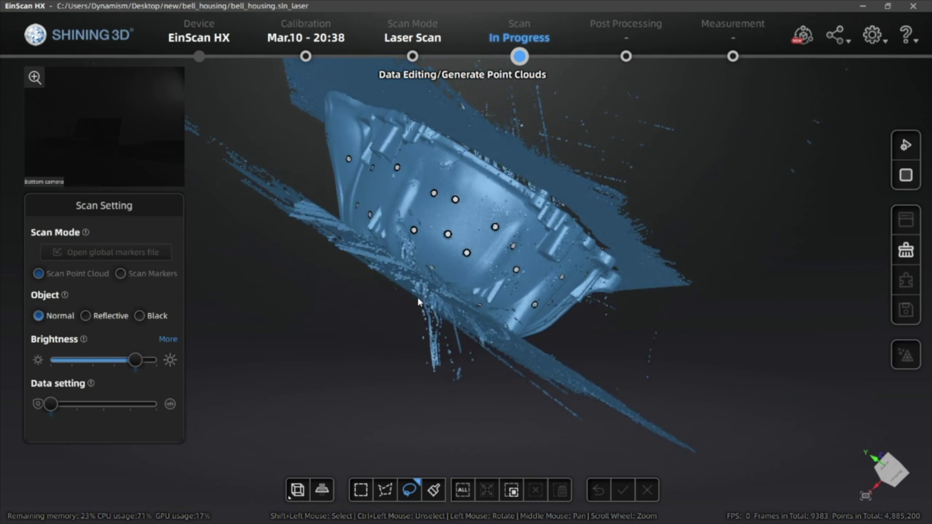
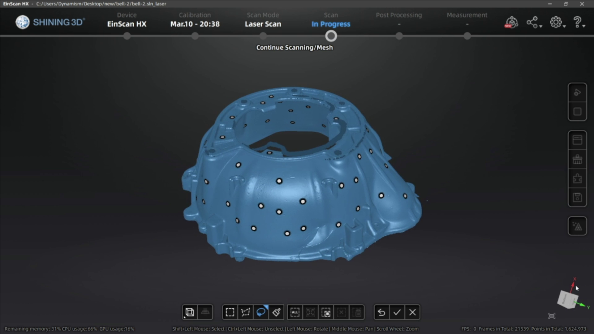
Now, click the play button again to begin scanning. Move the scanner around the object, rotating to help capture different angles. If you need to turn the object, pause the scanner and move it to a better position before resuming.
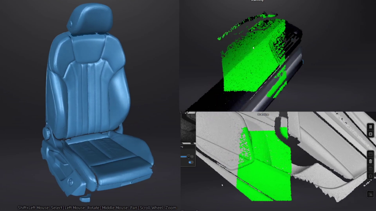
Once you have scanned your object and generated the point cloud data, you can then generate the mesh of your 3D scan. If you’re planning on using scan data for reverse engineering or QC you can export a non-watertight mesh, however for 3D printing you’ll need to make sure you get a watertight model for optimal results.
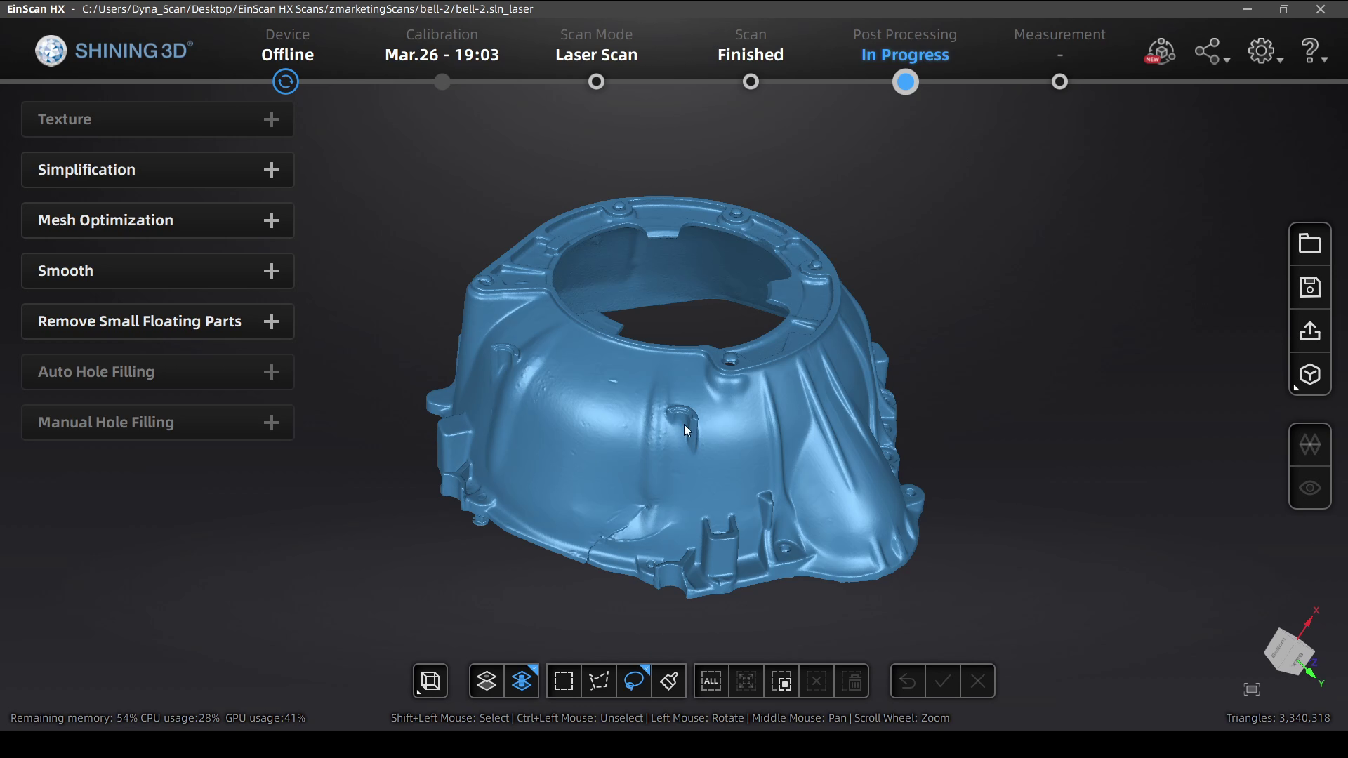
3. Mesh Cleanup
After you get your mesh data, there are a few different tools that available to help get your 3D model ready to be used.
First, you can select and delete data that you don’t need (much like in the other steps in the scanning process).
If the model is not watertight, or you deleted portions of your watertight model, you can also fill the holes manually by selecting each one, or automatically if there are too many to select individually.
Another useful tool is the ability to simplify the object, which is great for reducing the file size while still keeping most of the part quality. You can usually reduce the file by 40-60% without affecting the surface quality of your scan, and it’ll help a lot when you import this 3D model into another program or share it with others.
After you’re done with your edits, the mesh files can be exported as an STL, OBJ, 3MF, or PLY file for use in your reverse engineering process, measuring/QC workflow, or to send straight to your slicing software to 3D print!
The HX is the best industrial scanner thanks to it’s specialized blue LED rapid scan mode and high accuracy Laser Scan mode leveraging tracking dots for best accuracy.
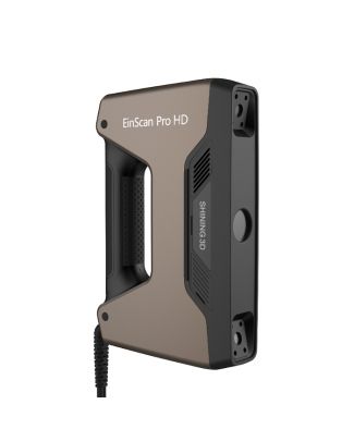
The Pro HD has a special blue LED light which helps at scanning slightly reflective or darker objects. An additional Color Pack camera can be added for full color scanning.
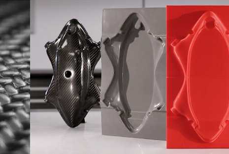
In this tutorial, we skip the process of using a pattern to create a mold and directly create a mold using 3D printing. This tutorial is a bare-bones carbon fiber process meant for those without the specialized equipment needed for more technical processes and high-temperature epoxies.
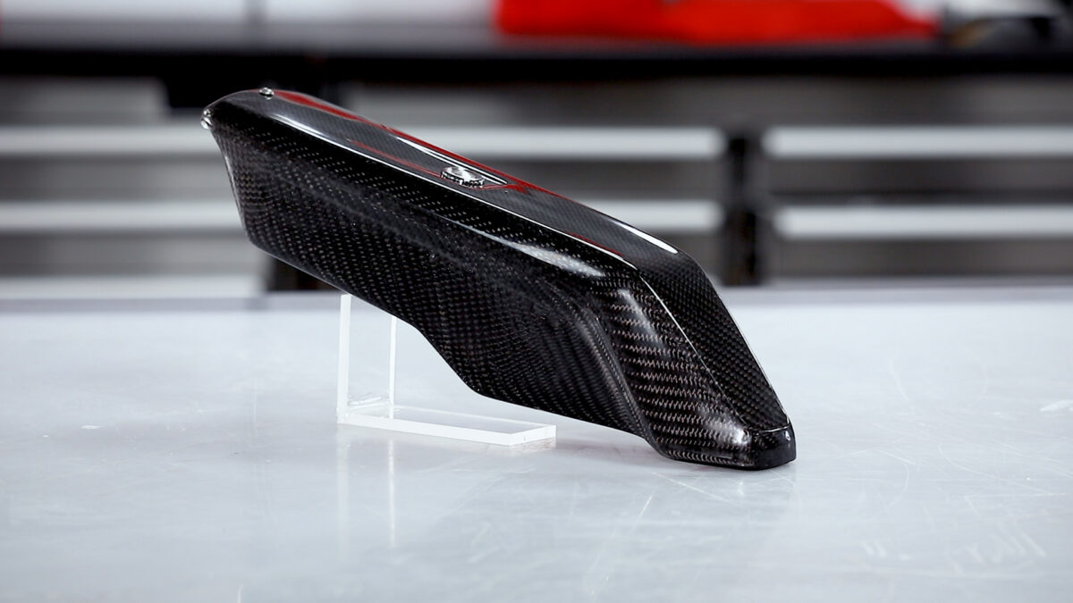
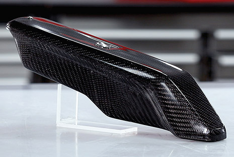
We will be taking a FFF print with the barriers already modeled and release-coating it before manufacturing the carbon fiber part using a simple hand layup process. Non-cosmetic parts can be used directly from the mold, however, the surface will be slightly compromised by the resolution of the 3D print and limitations of a hand layup process. To bring the finish up to a perfect standard the part can be coated in XCR coating resin and flatted and polished to a high-quality finish.
Material Compatibility
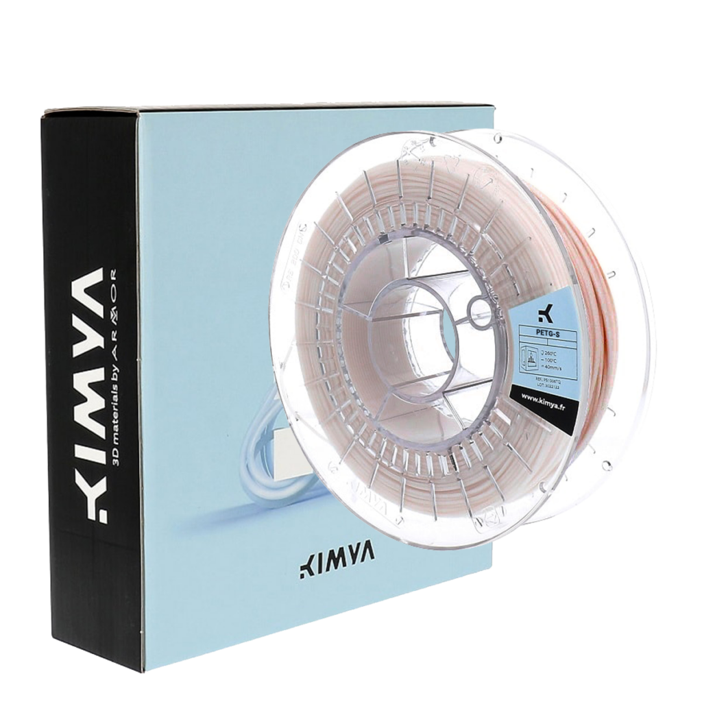
PET-G filament is highly recommended due to its good release properties with the epoxy resin. ABS should be avoided as a direct mold material as you may find if difficult to get a good release from epoxy resin.
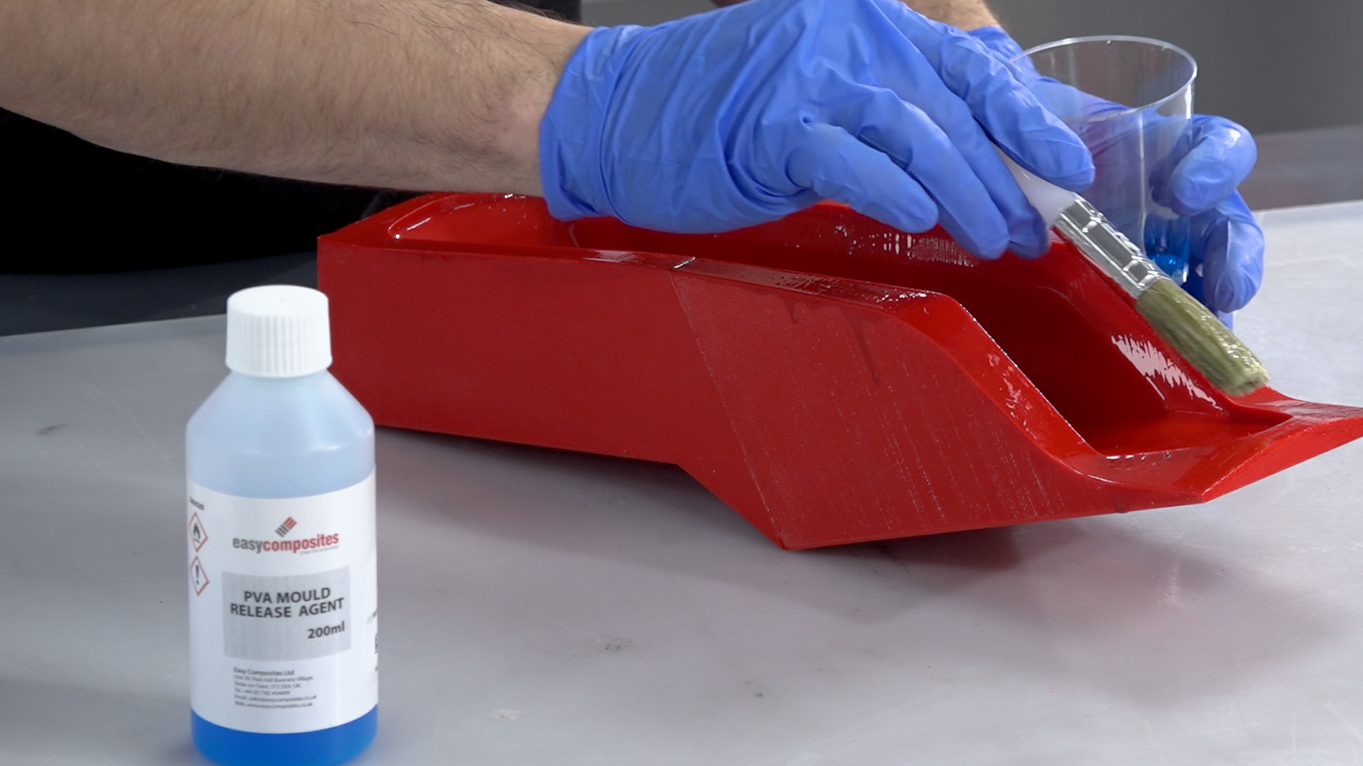
After 3D printing, the mold should be prepared with a release agent. The most reliable release agent for this process is PVA release agent, as it helps to smooth out layer-lines while providing a reliable release from the epoxy resin.
The resulting mold from this process will work with most conventional resin systems, such as epoxy polyester and vinylester. Generally molds made in this way are best suited to hand layup processing (with or without a vacuum bag). It would also be possible to process using resin infusion but due to 3D prints generally not being 100% airtight, an envelope bagging method may have to be used. Molds made with this process are not suitable for elevated temperature cures, as used in prepreg production, even when the HDT of the PETG is not theoretically exceeded, we have found the stress of the vacuum bag will lead to excessive warping and distortion.
Materials & Equipment Needed
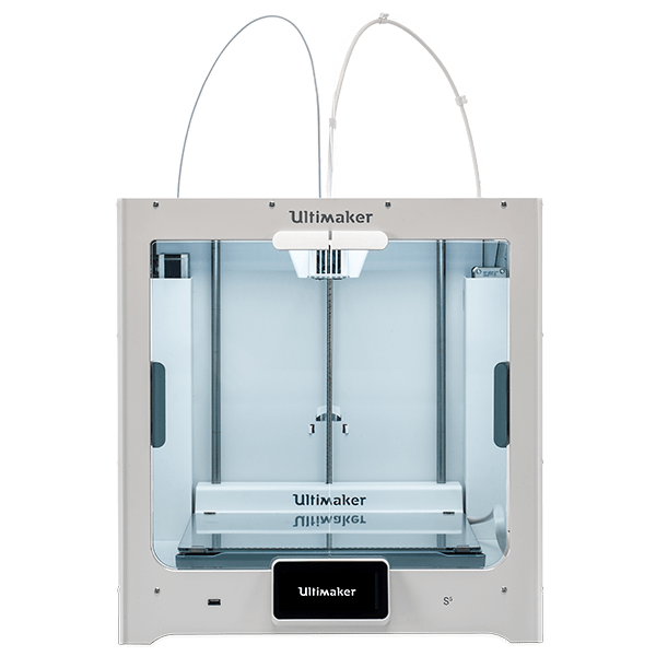
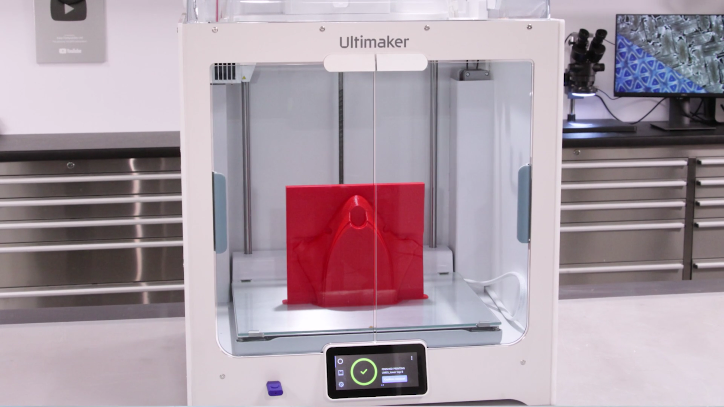
3D Printed Part – For this tutorial, we use the Ultimaker S5 which is an affordable, end-to-end 3D printer with hundreds of ready-to-print materials.
XC110 210g 2×2 Prepreg Carbon Fiber: We are using three plies in this project but any dry composite reinforcement can be used.
EL2 Laminating Epoxy: Which is specifically designed for wet layup processing and offers excellent strength and wet-out performance. The back of the part is then finished with our Economy Peel-Ply which provides a neat inner surface.
XCR Coating & NW1 Polishing Compound (optional): Use these to post-process your carbon fiber part, providing a better cosmetic finish on your end product.
Ultimaker S5
A large, easy-to-use 3D printer with massive, ready-to-print material ecosystem.
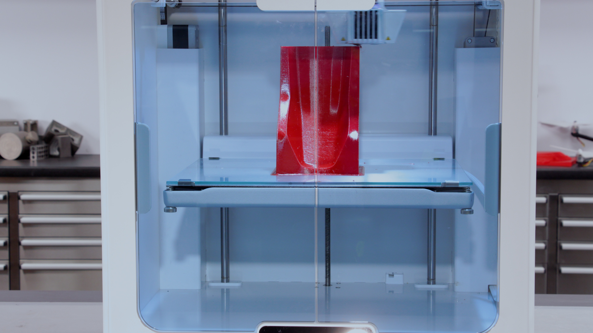
Design and 3D print your mold with any flanges or extensions required to aid in the layup. We suggest using PET-G for directly printed molds due to its reliable release properties. Printing at a higher resolution will provide a smoother mold surface that is easier to release from. For this project we printed with ‘standard’ CURA Slicer settings with a 0.15mm layer height. If possible, orient the part so that the layers are printed parallel to the direction of release of the part, this will reduce the mechanical lock presented by the print surface. That being said, as long as you have a draft-angle of 5deg or greater you can still get a good release, even if the layer-lines are perpendicular to the release direction.
For larger molds, BigRep 3D Printers provide build volumes up to 1m3, or your design can be printed in sections and then bonded together with an appropriate adhesive. Although, PET-G may have some bonding issues due to its release properties.
2. Apply the Release Agent
Although PET-G will offer an inherent release with epoxy resins a release agent is still required to ensure that the part will separate from the mold. We recommend PVA release agent, as it offers a very fast and reliable release in this process. PVA is applied in a single coat either by wiping or brushing an even film over the mold surface. This coating should be liberal but not so thick that it causes runs. Once applied, the PVA release agent should be allowed to dry as room temperature, typically this will take around 30 minutes.
3. Laminate the Part
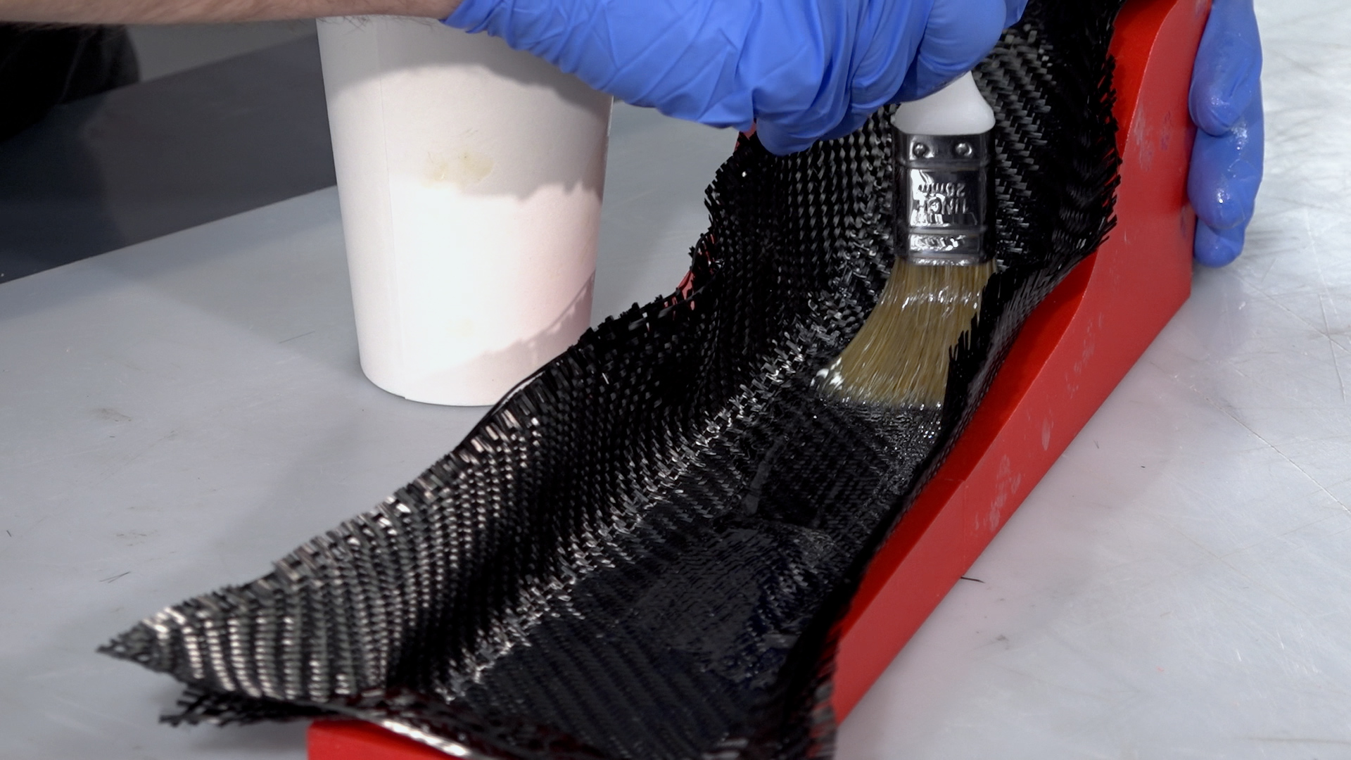
For this project, we are using the EL2 laminating resin. Be sure to accurately and thoroughly mix the resin with its hardener. It is best practice to pour from the first container into a second and mix again to ensure there is no unmixed resin.
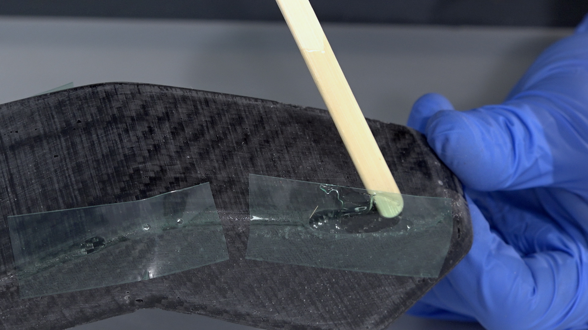
Before laying the carbon, the mold should be coated in a film of resin. When hand laminating you should, wherever possible, lay the carbon onto the resin and wet out the fabric with resin from underneath. This will help to ensure proper wet-out and will reduce air entrapment. For small intricate parts, a laminating brush will be needed but for larger or flatter moldings, a roller or squeegee can aid the wetting out. For a wet lay-up you are typically aiming for a fibre to resin fraction of 1:1 so for every 100g of fibre you will use approximately 100g of resin.
With parts 3mm thick or less, it is usually possible to laminate all of the layers in one single operation. For thicker parts, it may be necessary to divide the layup into multiple laminations to reduce the effects of shrinkage and the possibility of a thermal runaway or ‘exotherm’.
On this project, after the reinforcement is laid, a layer of peel-ply is used as a final ply to create a neat finish on the inside of the part, which also provides a good surface for subsequent bonding operations. With the peel-ply laminated, the part can then be left to cure at ambient temperature. Cure times will vary depending upon the hardener speed and the room temperature but will typically range between 12 and 48hrs.
CAUTION: Do not leave the mixed EL2 resin in the bottom of the mixing cup if deeper than 5mm. This can undergo a thermal runaway which can be potentially dangerous. Excess resin should be poured into a tray to increase the surface area and/or the container should be moved to a safe outdoor location in case of overheating.
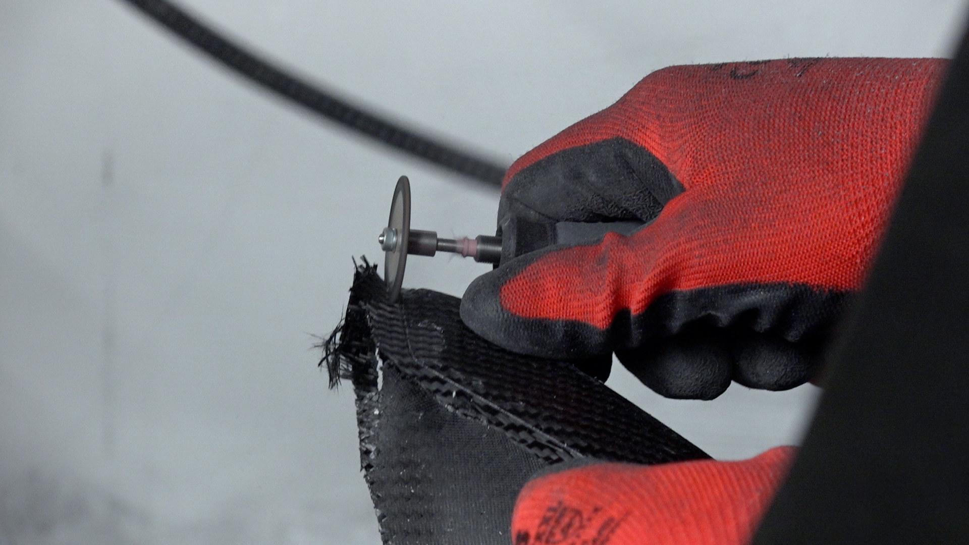
4. Trim
After demolding, trim and finish to give a clean edge to the part. For our project, we used a Dremel type tool fitted with a 32mm Permagrit cut-off wheel which is an excellent all-round trimming tool and lasts for hours of continuous use. The edges were trued up using a sanding block and finished with 240grit paper. If you are happy with the results as left by the XCR coating, the part could be used as is but generally, sanding and polishing the part would be preferred as it will leave a more consistent and professional finish.
Free Tutorial
Download This Carbon Fiber Tutorial
Learn how to create carbon fiber molds faster and cheaper with 3D printing
In order to achieve a good cosmetic finish without pinholes and print layer-lines, the part can be coated with a resin or clear-coat. To prepare the part, the surface will need to be abraded with 400grit wet and dry sandpaper to provide a good key for the coating.
If your part has any voids or large pinholes, use resin to fill them. For larger voids, a dam created from flash release tape can help to hold the resin back from running out, then use either the EL2 laminating resin or the XCR coating resin to fill it. After the repairs have been made, they should be left to cure and then sanded back in flat with 400grit paper to level with the surface of the part.
6. Coat with XCR Coating Resin
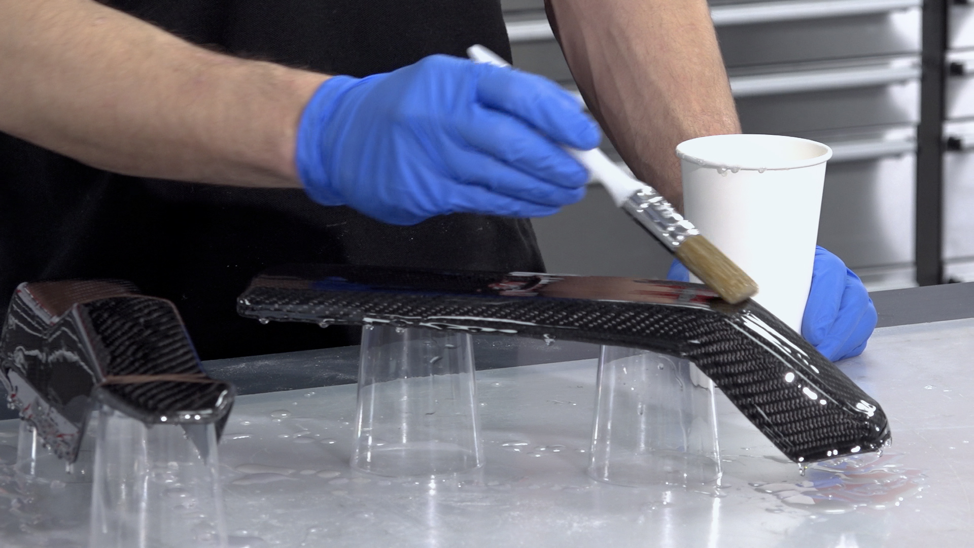
With the part fixed and sanded, it can now be coated to provide a smooth glossy and durable finish. It is possible to use a clear-coat automotive spray but for this but in this project, we are using the XCR coating resin which will provide a very durable finish and can easily be applied with a brush.
Coat your part in XCR epoxy coating resin—typically around 300 grams per square meter for each coat. Plan on mixing more than is needed to allow for wastage in mixing cups, brushes, etc. The hardener should be added to the resin in the exact ratio of 100:35, as accurately as possible for small batches of resin scales (within one-tenth of a gram accuracy will help). Mix the resin in one cup, then transfer to a second cup and mix again to ensure that there is no unmixed resin trapped.
Use a brush to apply a thin, even coat over the surface. Do not overload the surface as this will lead to runs in the coating. After applying the coat, check a few minutes later for any runs, removing any excess resin a brush.
Depending upon the finish left by the first coat, as second may be required if any of the surface irregularity has not been covered. The second coat should be applied when the first has reached the B-stage. You can identify the B-stage by touching your print with a gloved finger, it should be tacky but leave no residue, typically around three hours for the XCR, but may vary depending upon room temperature. After your second application the resin should be left to fully cure, about 12–24 hours depending upon temperature.
CAUTION: Do not leave the mixed XCR resin in the bottom of the mixing cup if deeper that 5mm. This can undergo a thermal runaway, which will potentially be hazardous. Excess resin should be poured into a tray to increase the surface area and/or the container should be moved to a safe outdoor location in case of overheating.
7. Sand & Polish
If you are happy with the results as left by the XCR coating, the part could be used as is but generally, sanding and polishing the part would be preferred as it will leave a more consistent and professional finish.
The sanding process should start with the finest grade of paper that can be used to quickly flatten down the surface—generally either 400 or 800 grit wet and dry. This is best done wet to prevent the paper from clogging, and the grades should be worked through to a minimum of 1200 grit. Use a sanding block for flat areas and single curvatures to maintain an even, flat face and the paper along can be used for the remaining curved areas. Whenever changing to a finer grade of abrasive, clean the pattern and change the water to prevent scratches from particles of the previous grade.
After the 1200 grit (or finer), continue with the final polish using the NW1 polishing compound. Unless your part is very small, this is best done with a foam pad on a polishing machine.
Unlike many compounds, the NW1 does not need water and does not quickly dry out. This particular compound is self-diminishing—the more you work it, the finer it gets. You should be able to achieve a full mirror polish in one step. Once buffed, the last residue of the compound can be wiped away with a microfiber cloth, which should reveal a mirror-like polish on your finished pattern.
Choosing the right 3D printer doesn’t have to be difficult. Find the perfect printer for your application. This in-depth guide covers pricing, materials, dimensional accuracy, and more.
Learn how to create a production-ready molds for carbon fiber parts using a 3D printed patterns / masters. This tutorial can be followed to make a mold suitable for wet lay-ups, vacuum bagging, resin infusion, and prepreg manufacturing techniques. In addition, the resulting mold can be used for both high temperature and ambient temperature epoxies. If you would like to 3D print a carbon fiber mold directly, new tutorials are coming soon. Be sure to subscribe and save our Carbon Fiber page for upcoming tutorials.
Required Tools & Materials
3D Printing & Mold Making
3D Printer – In this project we use the Ultimaker S5 due to size and affordability.
PLA or ABS Filament – These materials offer good adhesion to the coating resin
XCR Epoxy Coating Resin – Applied at around 300-500 grams per square meter of 3D print, for smaller patterns you will need to factor a larger amount due to wastage (in mixing cups, brushes, etc.)
800 & 1200 Grit Sandpaper – Wet and dry needed
NW1 Cutting Compound – An advanced ‘super cutting’ compound designed for polishing composite molds
Your part should be modeled to include flange barriers and printed in PLA. Faster print settings with larger layer lines, 0.2mm layer height or above, can be used here as the layer lines will be easily covered by the following epoxy coating step. Our shell thickness was set to 0.8 mm with a 20% infill. If your project demands higher accuracy, a higher resolution and smaller print print cores/nozzles can be used. For more dimensionally critical applications, the surface of the part should be offset by around 0.25 mm to compensate for the thickness of the epoxy coating.
For extra large patterns, Dynamism offers a number of large format 3D printers up to 1m3. Also, patterns can be printed in sections and then bonded together with an appropriate adhesive. For PLA, Cyanoacrylate (super glue) and epoxy adhesives work well.
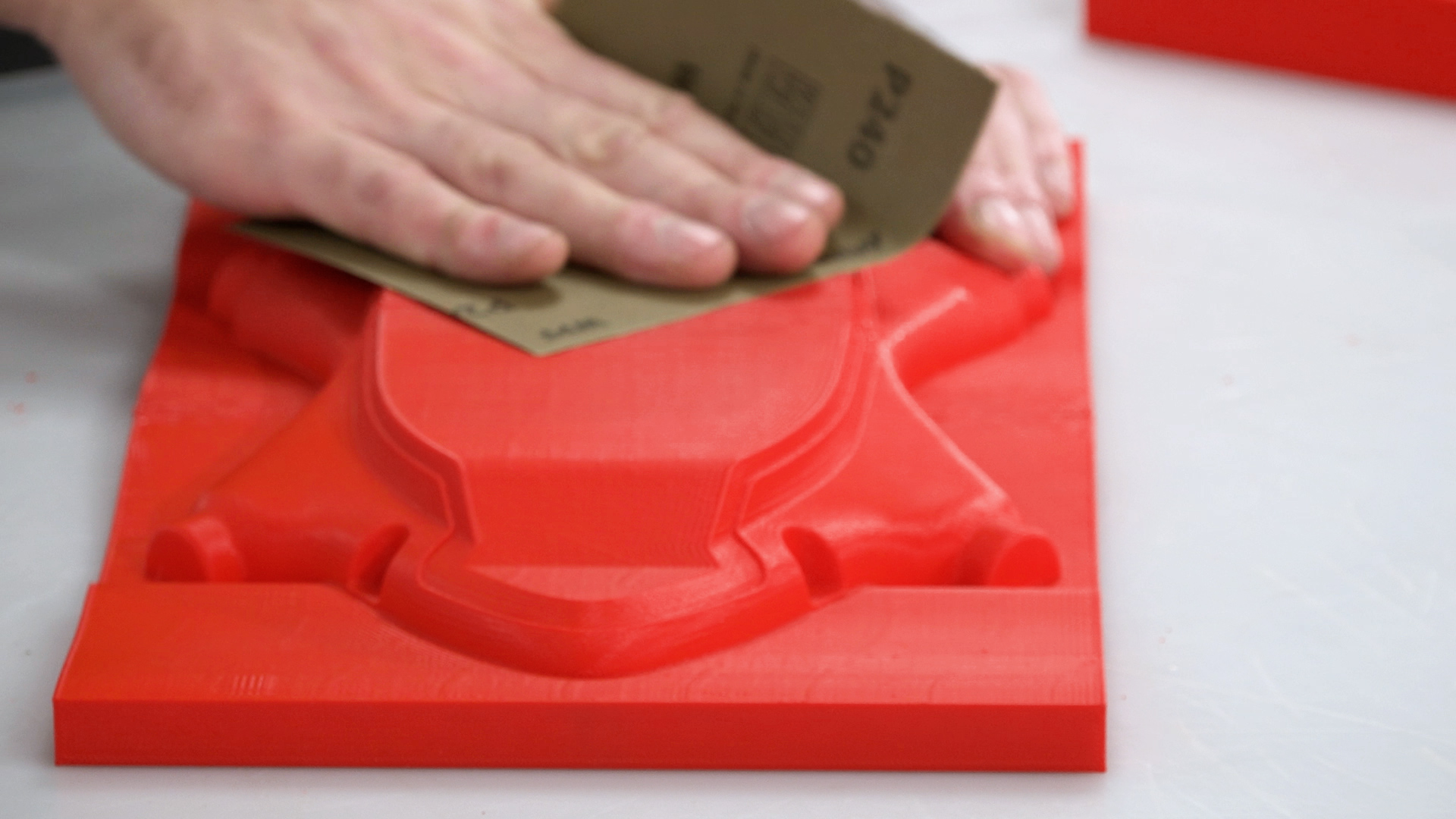
2. Sand The Pattern
Since we are going to be making a mold, the 3D printed part’s surface needs to be smoothed and sealed with epoxy. Without this step, the pattern will be difficult to remove from the mold and the surface finish of the resulting mold will retain the imperfections from the 3D print. To prepare the pattern for coating, it should first be abraded with 240 grit sandpaper to remove any high spots or blemishes while providing a good key for the epoxy coating to bond to.
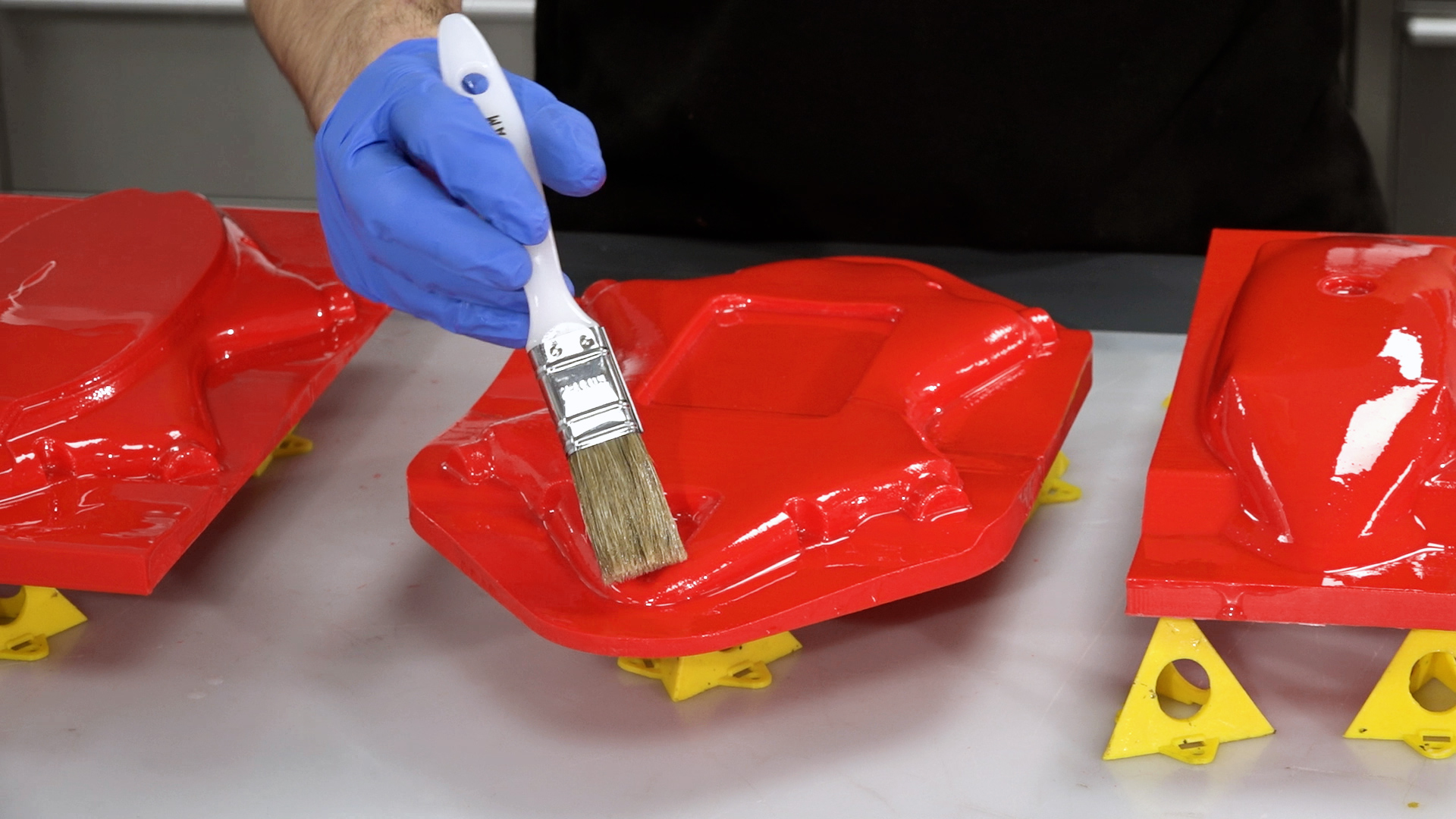
3. Coat With XCR Coating Resin
Next, you will need to coat your pattern in XCR epoxy coating resin—typically around 300 grams per square meter for each coat. Plan on mixing more than is needed to allow for wastage in mixing cups, brushes, etc. The hardener should be added to the resin in the exact ratio of 100:35, as accurately as possible for small batches of resin scales (within one-tenth of a gram accuracy will help). Mix the resin in one cup, then transfer to a second cup and mix again to ensure that there is no unmixed resin trapped.
Use a brush to apply a thin, even coat over the surface. Do not overload the surface as this will lead to runs in the coating. After applying the coat, check a few minutes later for any runs, removing any excess resin a brush.
For most patterns, two coats of resin will be needed. The second coat should be applied when the first has reached the B-stage. You can identify the B-stage by touching your print with a gloved finger, it should be tacky but leave no residue, typically around three hours for the XCR, but may vary depending upon room temperature. After your second application the resin should be left to fully cure, about 12–24 hours depending upon temperature.
CAUTION: Do not leave the mixed XCR resin in the bottom of the mixing cup if deeper that 5mm. This can undergo a thermal runaway, which will potentially be hazardous. Excess resin should be poured into a tray to increase the surface area and/or the container should be moved to a safe outdoor location in case of overheating.
4. Flatting & Polishing the XCR Coating
It is possible to jump directly to the next step but if you require a precise finish, flatting and polishing is advised. The flatting process should start with the finest grade of paper that can be used to quickly flatten down the surface—generally either 400 or 800 grit wet and dry. This is best done wet to prevent the paper from clogging, and the grades should be worked through to a minimum of 1200 grit. Use a sanding block for flat areas and single curvatures to maintain an even, flat face and the paper along can be used for the remaining curved areas. Whenever changing to a finer grade of abrasive, clean the pattern and change the water to prevent scratches from particles of the previous grade.
After the 1200 grit (or finer), continue with the final polish using the NW1 polishing compound. Unless your pattern is very small, this is best done with a foam pad on a polishing machine.
Unlike many compounds, the NW1 does not need water and does not quickly dry out. This particular compound is self-diminishing—the more you work it, the finer it gets. You should be able to achieve a full mirror polish in one step. Once buffed, the last residue of the compound can be wiped away with a microfiber cloth, which should reveal a mirror-like polish on your finished pattern.
Free Tutorial
Download This Carbon Fiber Tutorial
Learn how to create carbon fiber molds faster and cheaper with 3D printing
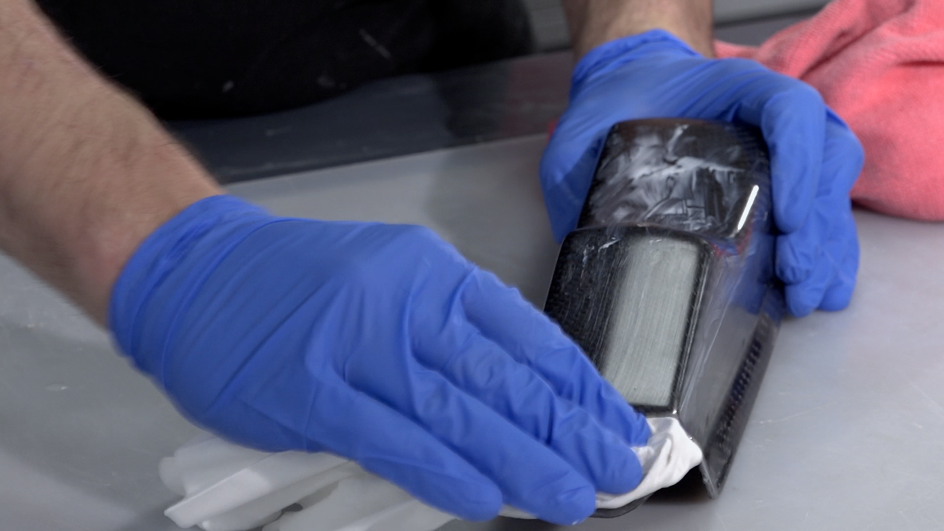
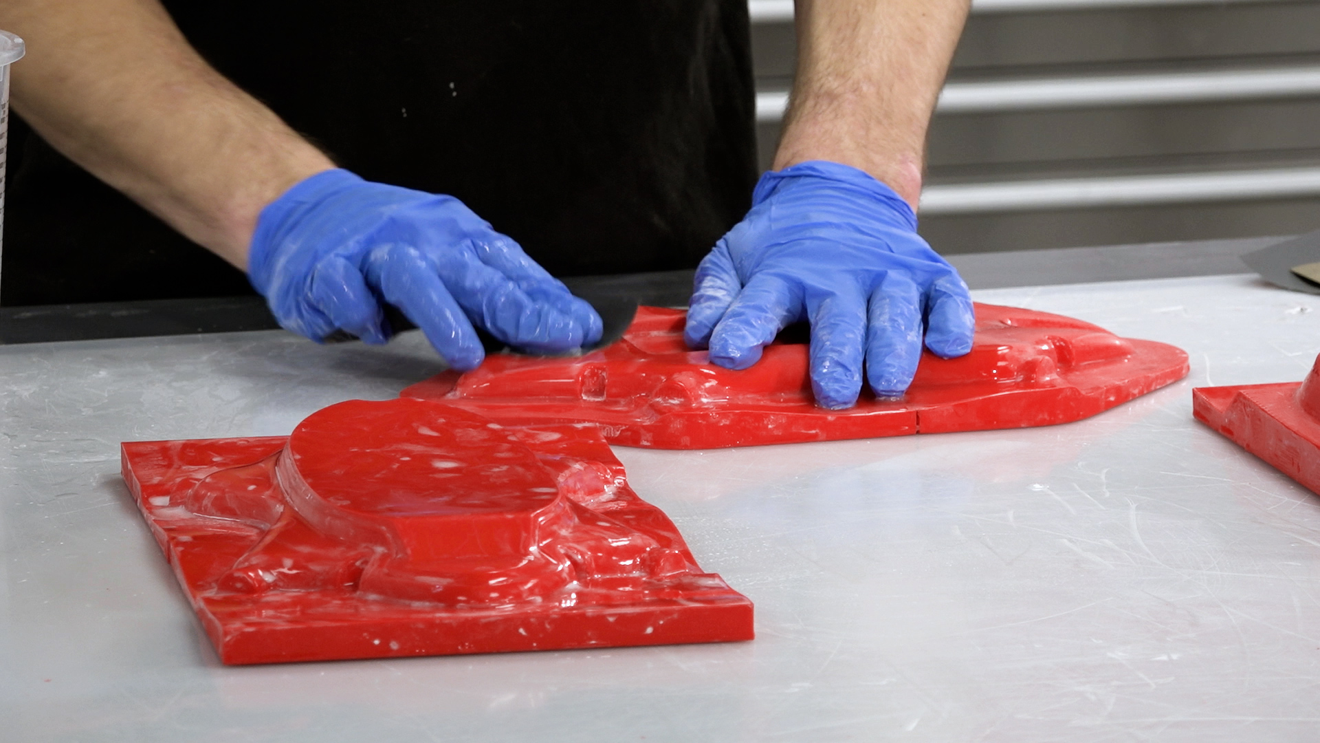
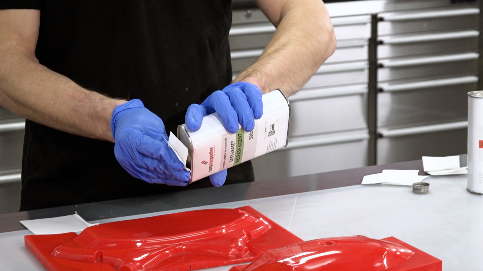
Before making the mold, coat the pattern with release agent. Most composite release systems, such as wax and PVA, can be used, but we recommend the Easy-Lease™ Chemical Release Agent. Apply pattern cleaning and release agent application in a well-ventilated area. After cleaning the pattern surface, apply the release agent in a thin film over the surface using a small piece of lint-free cloth.
Once the film begins to evaporate (5–30 seconds), use a second piece of cloth lightly in a circular motion to remove excess.
For new patterns, apply at least six coats, leaving a minimum of 15 minutes between each application. Leave the final coat for at least one hour before laminating the mold. It is important to use lint-free solvent application wipes as normal tissue papers can be attacked by the solvent and leave smearing. It is also important to use a fresh piece of cloth for each coat to avoid contaminating the release agent with partly cured material from the previous cloth.
6. Create the Mold
We are using the high temperature version of our epoxy mold making system, which comprises of the EG160 gelcoat and the EMP160 mold making paste. However, patterns made using this technique can be used to make molds using any conventional ambient temperature cure mold making process.
Applying the gelcoat: The EG160 Epoxy Tooling Gelcoat is mixed carefully and fully according to the instructions. In this tutorial, we will be “double-gelling” whereby the gelcoat is applied in two even applications.
The first application is thoroughly mixed and applied directly onto the prepared pattern at a thickness of approximately 500 grams per square meter, or around 0.5mm. The first application is then allowed to cure to the B-stage, where it is firm but still tacky. The exact timing of this will vary according to temperature, but this will be around five hours at 20°C (68°F).
Once the first application has cured to the B-stage, a second application is applied, aiming to keep the gelcoat as smooth and even as possible. This second layer of gelcoat is now also cured to the B-stage.
As soon as the second application has cured to the B-stage, the main reinforcement for the mold can be applied. It is very important to not allow the gelcoat to cure past the B-stage, otherwise it will become too hard and dry and the laminating paste will not be able bond properly to it. In the case of the high temperature system, we strongly recommend applying a thin coat of EG160 gel immediately prior to the mold making paste to act as a coupling coat, which will promote the bond of the interface.
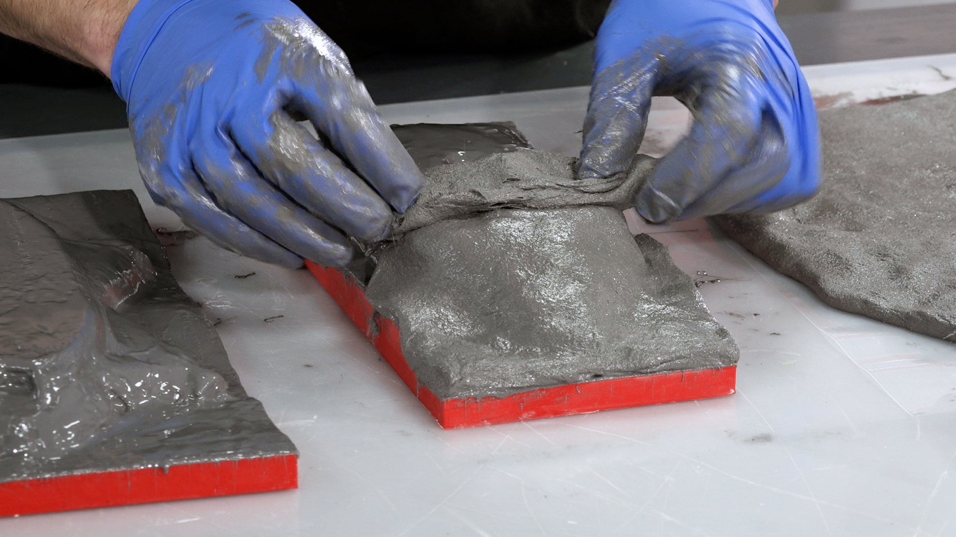
EMP160 is an epoxy-resin based laminating paste. The paste contains resin, filler, and chopped glass fiber strands for reinforcement and can be used on its own as the main reinforcement for the mold. The advantage to a laminating paste is that the fine, paste-like material is very easy to work into corners and details, reducing the risk of air-voids and providing a fast and reliable means of reinforcing an epoxy-based mold.
EMP160 is thoroughly mixed according to the instructions and then applied directly onto the wet coupling coat of EG160 gelcoat at a thickness of around 10mm before being left to fully cure for around 24 hours. Care should be taken to avoid trapped air under the reinforcement—it is generally best to tile the surface with smaller amounts.
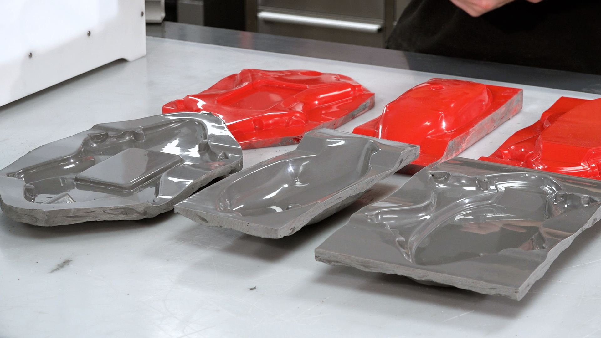
6. Separate the mold from the pattern and prepare
Once fully cured, the mold can be removed from the pattern. Removing any excess material from the perimeter will often help with the release—plastic wedges can be used to carefully separate the mold from the pattern.
In the case of this high temperature mold, we now need to complete a post-cure on the mold. This involves a steady ramp in temperature up to the service temperature to condition the mold—information on this cure profile can be found in the datasheet for the product. For ambient temperature use molds, this step is not normally necessary.
Prior to use, the mold is then coated with release agent in the same way as the pattern was coated.
2021 Edition
Professional 3D Printer Buyers Guide
Choosing the right 3D printer doesn’t have to be difficult. Find the perfect printer for your application. This in-depth guide covers pricing, materials, dimensional accuracy, and more.
We chose to make the final component using an out-of-autoclave prepreg process, which requires a vacuum and oven.
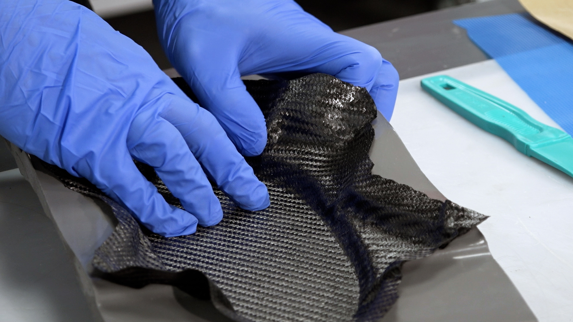
These parts are to be made with an extremely thin (0.25mm) laminate, which consists of only one ply of 210g XC110 prepreg carbon. The actual handling of the prepreg is relatively simple, but great care must be taken to ensure the material is properly down in the mold. Work systematically from the center lowest point so that you do not end up bridging over any corners or detail.
Laminating tools, called dibbers, can be used here to help press the prepreg down into the mold. These tools can be made by hand, bought ready-made, or by using edges of other tools (e.g., the handle on shears). It is key to ensure there are no bridges or voids. Laying up other pieces around tight corners or detail may lead to creasing of the material or it lifting. In these areas, composite snips can be used to make small cuts to allow the material to lap and conform to the mold.
8. Vacuum bag the part
As these parts are only one ply thick, the typical de-bulking processes that are normally used in prepreg laminating are not required. Instead, the part can be put straight into the final vacuum bag ready for cure, which starts by applying a non-perforated release film to the prepreg. It is essential that this layer, just like the laminate itself, is carefully pressed onto the mold surface without any bridges. Once on the mold surface, rub with a cloth to press the release film firmly onto the material. You can use flash release tape to help hold the film in place if necessary.
For this size part, it is only required to have breather on the underside and edge of the part to provide an air path. Not having breather on the material surface actually helps on complex shapes as the breather does not get in the way of the vacuum bag getting into the tight corners and detail.
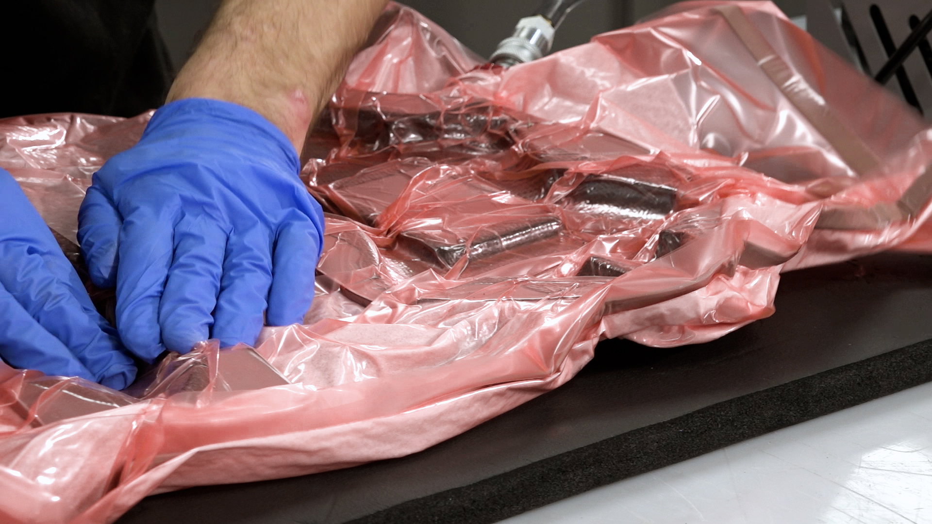
The bag being created is an envelope bag with the mold placed directly into the bag. This is common with production of smaller prepreg parts as it is possible to place several small parts into one big vacuum bag and cure them all together. The through bag connector is placed on one corner of the breather to ensure there is a continuous air path.
Start by pulling only a partial vacuum, stopping the pull as necessary to position and move the bagging film. This stage is critical to get the film into all the corners and recesses of the mold. Use creases of film to achieve this—as the vacuum increases, the spare film in the crease will be pulled into the corner, thus avoiding any bridging of the film. Once the bag is positioned correctly, a full vacuum can be pulled. Once a full vacuum is pulled, carry out a leak test for at least 10 minutes.
9. Oven cure the prepreg
With the bag pulled down and successfully leak tested, it can now be put in the oven to cure. Place the bag carefully in the oven, ensuring the bag cannot snag or catch on any edges, causing a puncture. Connect the vacuum line inside the oven and connect the pump to the assembly outside. You can now run the pump, allowing the bag to be maintained under full vacuum throughout the cure.
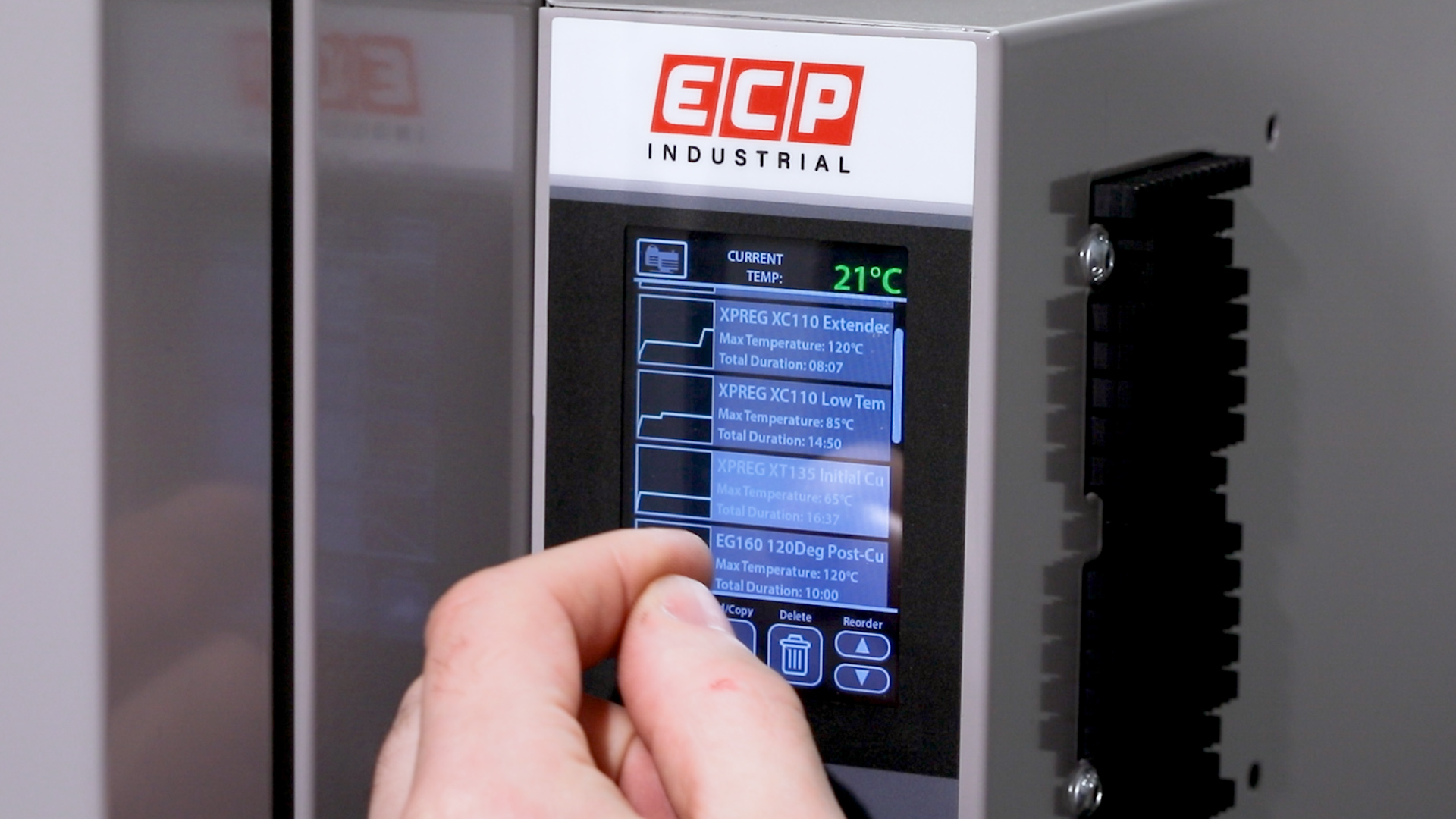
Close the oven doors, switch on the oven, and program the cycle you wish to use. Our OV301 oven has a simple touchscreen interface, allowing quick programming—all of our standard cure cycles are pre-programmed from the factory.
10. Demold the finished part
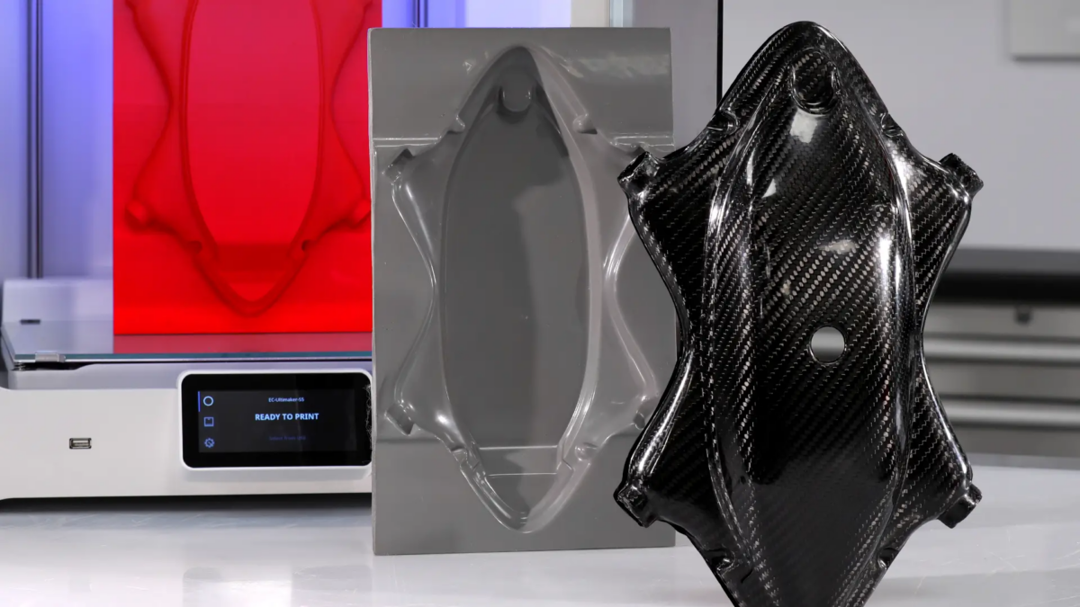
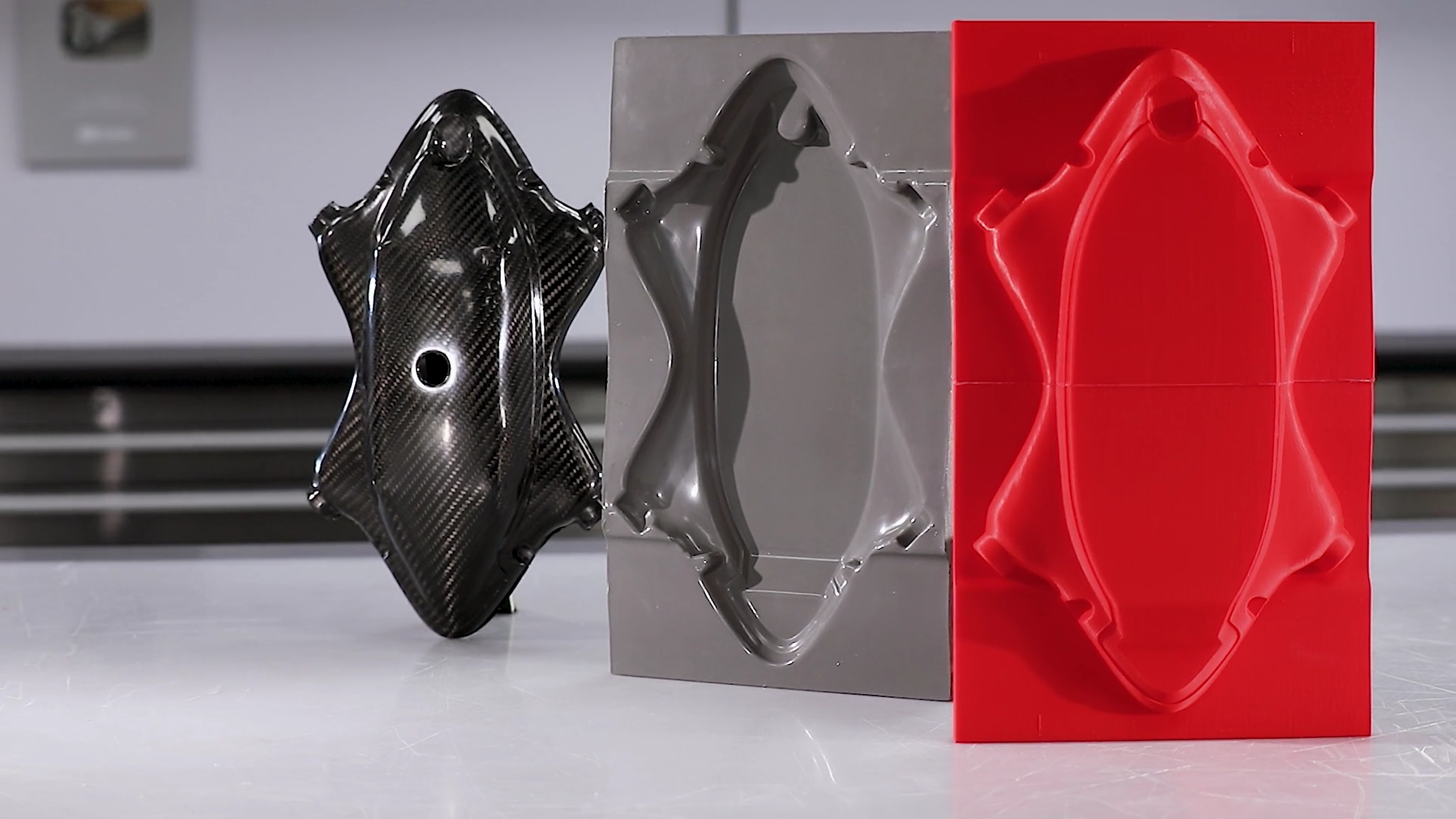
Once the oven curing cycle has completed, allow the part to fully cool to room temperature before demolding. Failure to do so can cause surface defects. Once cool, remove from the oven and remove the bagging film and breather. The release film should easily pull off. Using demolding wedges or other pointed items, taking care to avoid scratching the mold, carefully pry the edges of the part away from the mold. You may need to be systematically working around the mold to lift the part evenly until it comes free.
The demolded part then just needs trimming and finishing with a suitable rotary cutting tool and carbide abrasive tools and papers to give a nice, clean edge. The finished carbon fiber part can now be put into service.
Tutorial: How to 3D Print Molds for Carbon Fiber Parts
Save time and money by producing Carbon Fiber parts directly from 3D printed molds. Learn how to create strong beautiful components at a fraction of the cost and with less labor cost. In this tutorial you will learn:
How to use a 3d printer to directly print a mold suitable for ambient temperature processing.
Techniques to perform a simple hand layup in carbon fiber.
How to coat the finished part to provide a perfect cosmetic finish.
How To Create Carbon Fiber Molds From 3D Printed Patterns
Learn how to create production-ready carbon fiber molds from 3D printed patterns. This tutorial covers print settings and materials, carbon fiber materials and hardware, and in-depth, step-by-step instructions including:
How to use a 3D printer to create a pattern and prepare for mold making
How to create a mold from a 3D printed patterns using epoxy
How to use your mold to make a prepreg carbon fiber part