Transform Physical To Digital Inventory Using Additive Manufacturing
Eliminate waste, save time, and reduce the cost of carrying inventory by transforming indirect materials into digital inventory that can be manufactured on demand! In this success story you will:
Learn about Azoth’s Take One Make One inventory management system
Learn how TOMO can reduce on hand inventory, eliminate stockouts, and allow engineers to iterate designs with no obsolescence
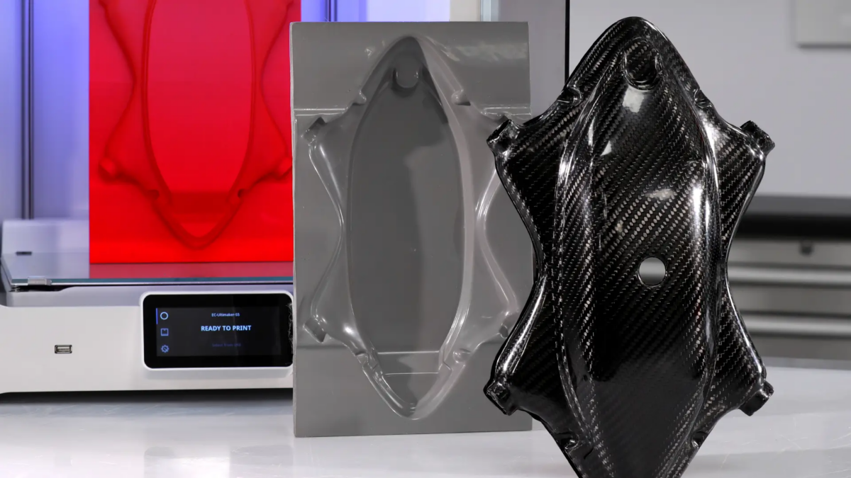
Learn how to create a production-ready molds for carbon fiber parts using a 3D printed patterns / masters. This tutorial can be followed to make a mold suitable for wet lay-ups, vacuum bagging, resin infusion, and prepreg manufacturing techniques. In addition, the resulting mold can be used for both high temperature and ambient temperature epoxies. If you would like to 3D print a carbon fiber mold directly, new tutorials are coming soon. Be sure to subscribe and save our Carbon Fiber page for upcoming tutorials.
Required Tools & Materials
3D Printing & Mold Making
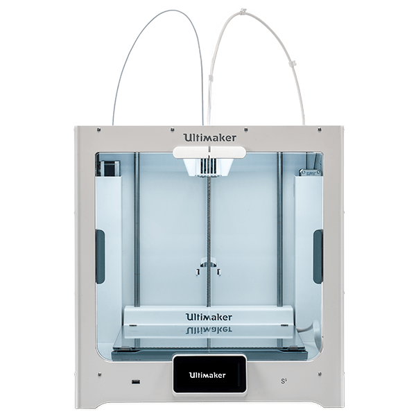
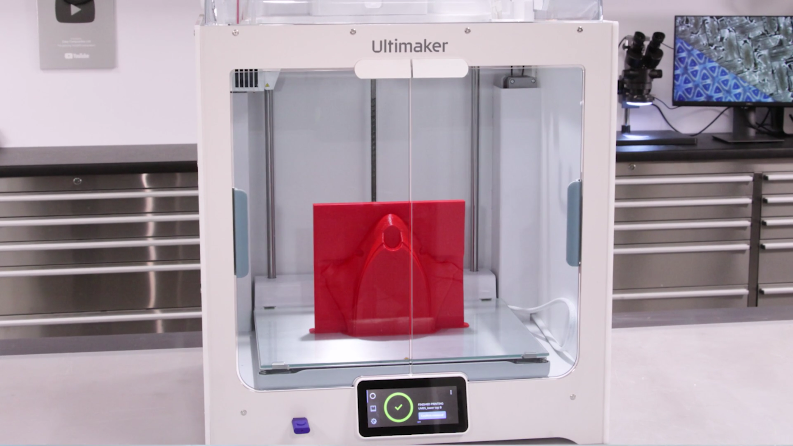
3D Printer – In this project we use the Ultimaker S5 due to size and affordability.
PLA or ABS Filament – These materials offer good adhesion to the coating resin
XCR Epoxy Coating Resin – Applied at around 300-500 grams per square meter of 3D print, for smaller patterns you will need to factor a larger amount due to wastage (in mixing cups, brushes, etc.)
800 & 1200 Grit Sandpaper – Wet and dry needed
NW1 Cutting Compound – An advanced ‘super cutting’ compound designed for polishing composite molds
Your part should be modeled to include flange barriers and printed in PLA. Faster print settings with larger layer lines, 0.2mm layer height or above, can be used here as the layer lines will be easily covered by the following epoxy coating step. Our shell thickness was set to 0.8 mm with a 20% infill. If your project demands higher accuracy, a higher resolution and smaller print print cores/nozzles can be used. For more dimensionally critical applications, the surface of the part should be offset by around 0.25 mm to compensate for the thickness of the epoxy coating.
For extra large patterns, Dynamism offers a number of large format 3D printers up to 1m3. Also, patterns can be printed in sections and then bonded together with an appropriate adhesive. For PLA, Cyanoacrylate (super glue) and epoxy adhesives work well.
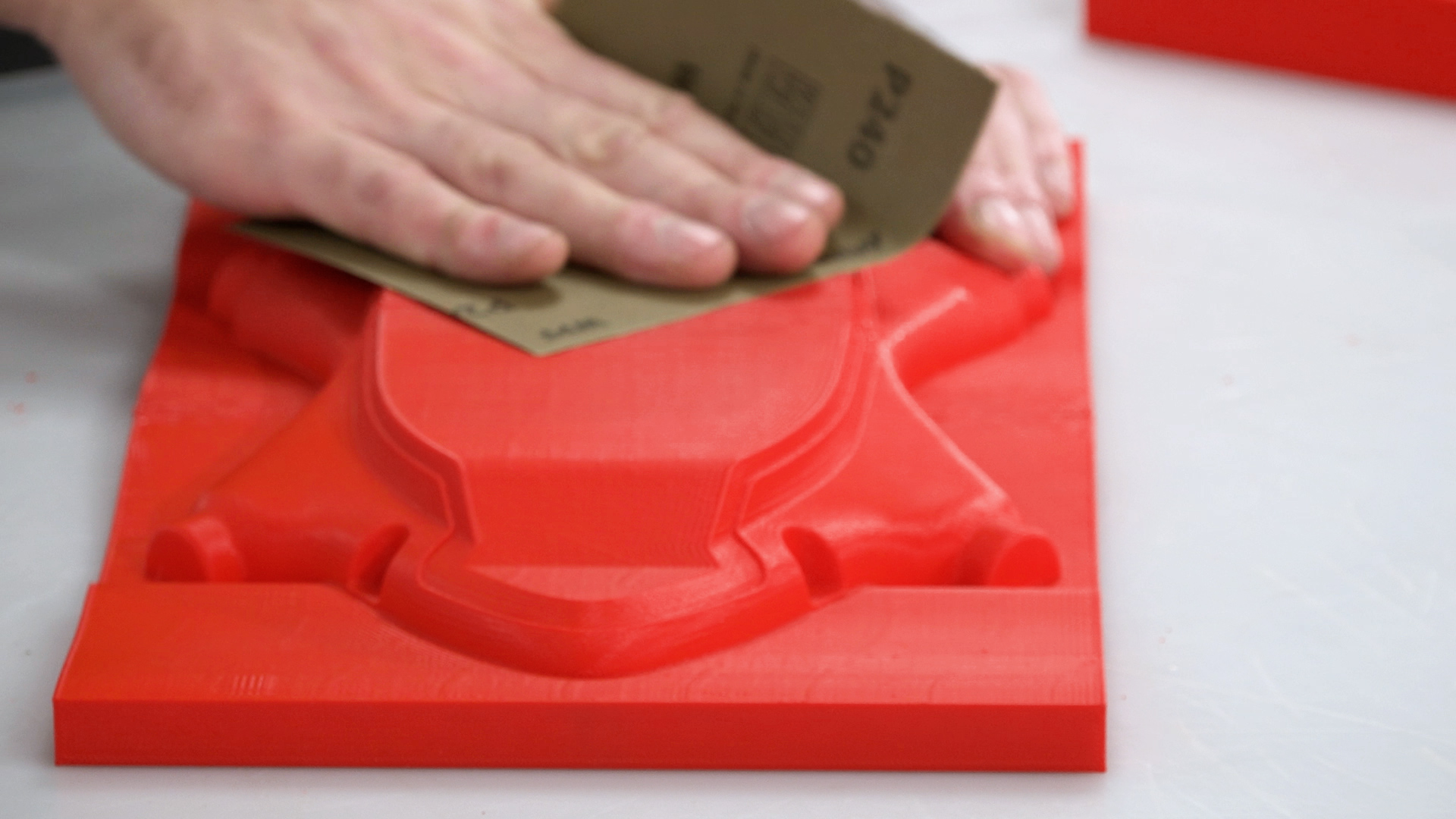
2. Sand The Pattern
Since we are going to be making a mold, the 3D printed part’s surface needs to be smoothed and sealed with epoxy. Without this step, the pattern will be difficult to remove from the mold and the surface finish of the resulting mold will retain the imperfections from the 3D print. To prepare the pattern for coating, it should first be abraded with 240 grit sandpaper to remove any high spots or blemishes while providing a good key for the epoxy coating to bond to.
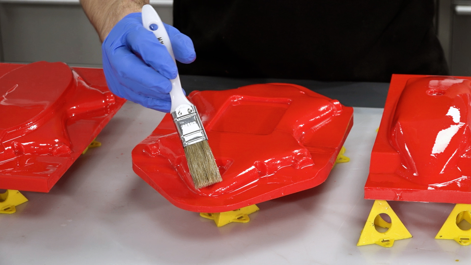
3. Coat With XCR Coating Resin
Next, you will need to coat your pattern in XCR epoxy coating resin—typically around 300 grams per square meter for each coat. Plan on mixing more than is needed to allow for wastage in mixing cups, brushes, etc. The hardener should be added to the resin in the exact ratio of 100:35, as accurately as possible for small batches of resin scales (within one-tenth of a gram accuracy will help). Mix the resin in one cup, then transfer to a second cup and mix again to ensure that there is no unmixed resin trapped.
Use a brush to apply a thin, even coat over the surface. Do not overload the surface as this will lead to runs in the coating. After applying the coat, check a few minutes later for any runs, removing any excess resin a brush.
For most patterns, two coats of resin will be needed. The second coat should be applied when the first has reached the B-stage. You can identify the B-stage by touching your print with a gloved finger, it should be tacky but leave no residue, typically around three hours for the XCR, but may vary depending upon room temperature. After your second application the resin should be left to fully cure, about 12–24 hours depending upon temperature.
CAUTION: Do not leave the mixed XCR resin in the bottom of the mixing cup if deeper that 5mm. This can undergo a thermal runaway, which will potentially be hazardous. Excess resin should be poured into a tray to increase the surface area and/or the container should be moved to a safe outdoor location in case of overheating.
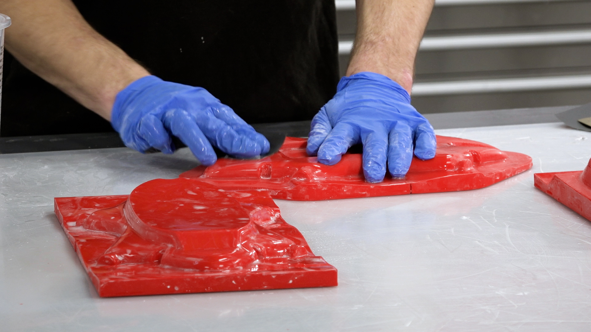
4. Flatting & Polishing the XCR Coating
It is possible to jump directly to the next step but if you require a precise finish, flatting and polishing is advised. The flatting process should start with the finest grade of paper that can be used to quickly flatten down the surface—generally either 400 or 800 grit wet and dry. This is best done wet to prevent the paper from clogging, and the grades should be worked through to a minimum of 1200 grit. Use a sanding block for flat areas and single curvatures to maintain an even, flat face and the paper along can be used for the remaining curved areas. Whenever changing to a finer grade of abrasive, clean the pattern and change the water to prevent scratches from particles of the previous grade.
After the 1200 grit (or finer), continue with the final polish using the NW1 polishing compound. Unless your pattern is very small, this is best done with a foam pad on a polishing machine.
Unlike many compounds, the NW1 does not need water and does not quickly dry out. This particular compound is self-diminishing—the more you work it, the finer it gets. You should be able to achieve a full mirror polish in one step. Once buffed, the last residue of the compound can be wiped away with a microfiber cloth, which should reveal a mirror-like polish on your finished pattern.
Free Tutorial
Download This Carbon Fiber Tutorial
Learn how to create carbon fiber molds faster and cheaper with 3D printing
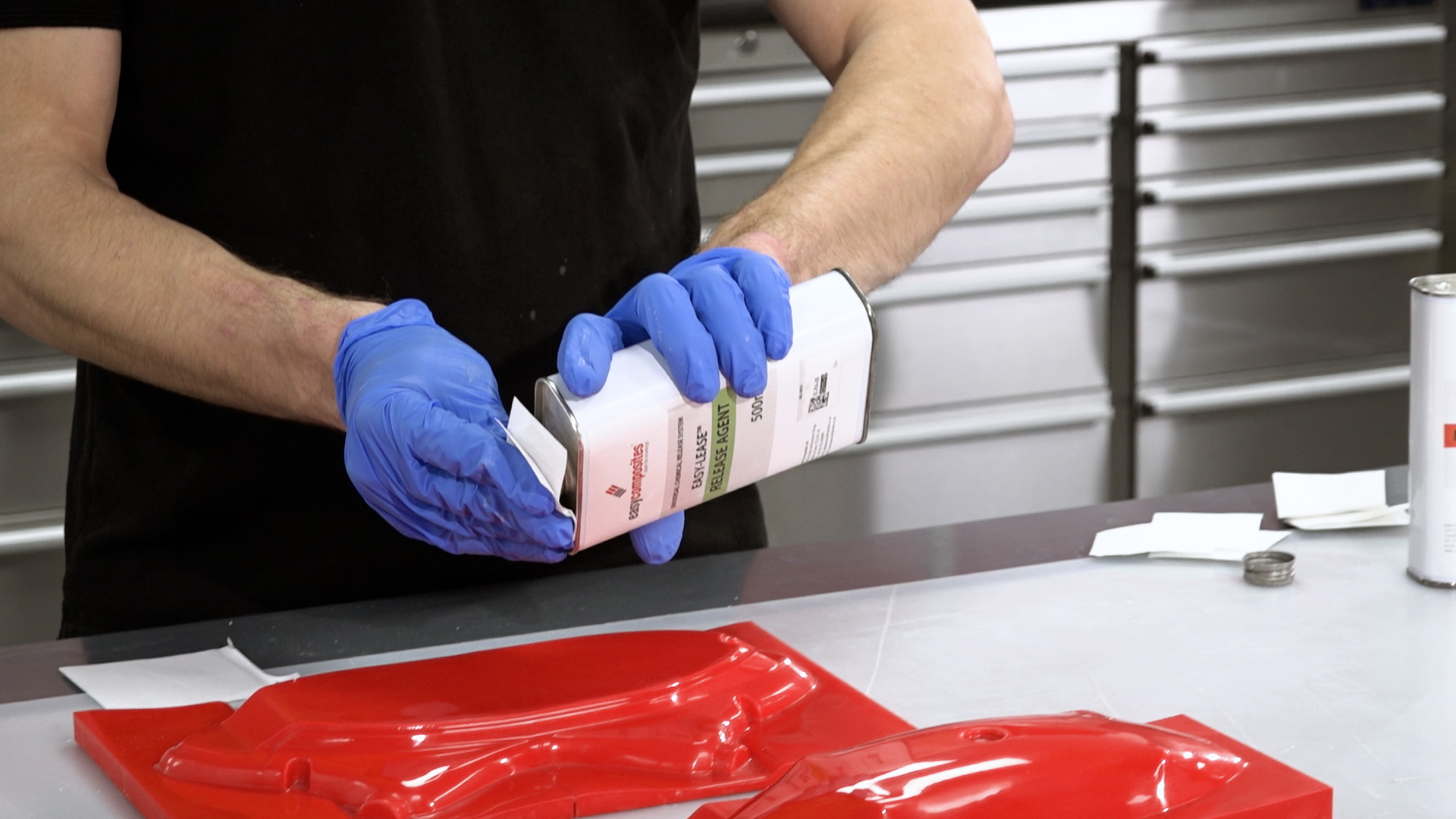
Before making the mold, coat the pattern with release agent. Most composite release systems, such as wax and PVA, can be used, but we recommend the Easy-Lease™ Chemical Release Agent. Apply pattern cleaning and release agent application in a well-ventilated area. After cleaning the pattern surface, apply the release agent in a thin film over the surface using a small piece of lint-free cloth.
Once the film begins to evaporate (5–30 seconds), use a second piece of cloth lightly in a circular motion to remove excess.
For new patterns, apply at least six coats, leaving a minimum of 15 minutes between each application. Leave the final coat for at least one hour before laminating the mold. It is important to use lint-free solvent application wipes as normal tissue papers can be attacked by the solvent and leave smearing. It is also important to use a fresh piece of cloth for each coat to avoid contaminating the release agent with partly cured material from the previous cloth.
6. Create the Mold
We are using the high temperature version of our epoxy mold making system, which comprises of the EG160 gelcoat and the EMP160 mold making paste. However, patterns made using this technique can be used to make molds using any conventional ambient temperature cure mold making process.
Applying the gelcoat: The EG160 Epoxy Tooling Gelcoat is mixed carefully and fully according to the instructions. In this tutorial, we will be “double-gelling” whereby the gelcoat is applied in two even applications.
The first application is thoroughly mixed and applied directly onto the prepared pattern at a thickness of approximately 500 grams per square meter, or around 0.5mm. The first application is then allowed to cure to the B-stage, where it is firm but still tacky. The exact timing of this will vary according to temperature, but this will be around five hours at 20°C (68°F).
Once the first application has cured to the B-stage, a second application is applied, aiming to keep the gelcoat as smooth and even as possible. This second layer of gelcoat is now also cured to the B-stage.
As soon as the second application has cured to the B-stage, the main reinforcement for the mold can be applied. It is very important to not allow the gelcoat to cure past the B-stage, otherwise it will become too hard and dry and the laminating paste will not be able bond properly to it. In the case of the high temperature system, we strongly recommend applying a thin coat of EG160 gel immediately prior to the mold making paste to act as a coupling coat, which will promote the bond of the interface.
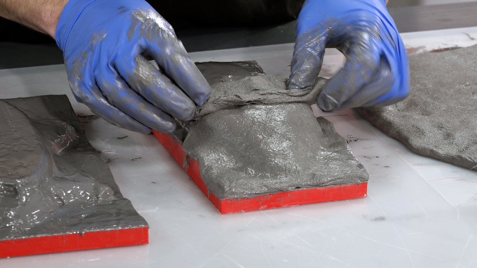
EMP160 is an epoxy-resin based laminating paste. The paste contains resin, filler, and chopped glass fiber strands for reinforcement and can be used on its own as the main reinforcement for the mold. The advantage to a laminating paste is that the fine, paste-like material is very easy to work into corners and details, reducing the risk of air-voids and providing a fast and reliable means of reinforcing an epoxy-based mold.
EMP160 is thoroughly mixed according to the instructions and then applied directly onto the wet coupling coat of EG160 gelcoat at a thickness of around 10mm before being left to fully cure for around 24 hours. Care should be taken to avoid trapped air under the reinforcement—it is generally best to tile the surface with smaller amounts.
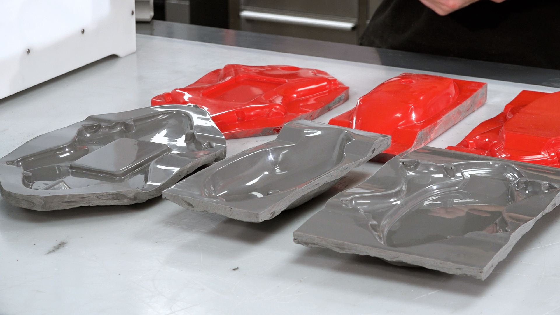
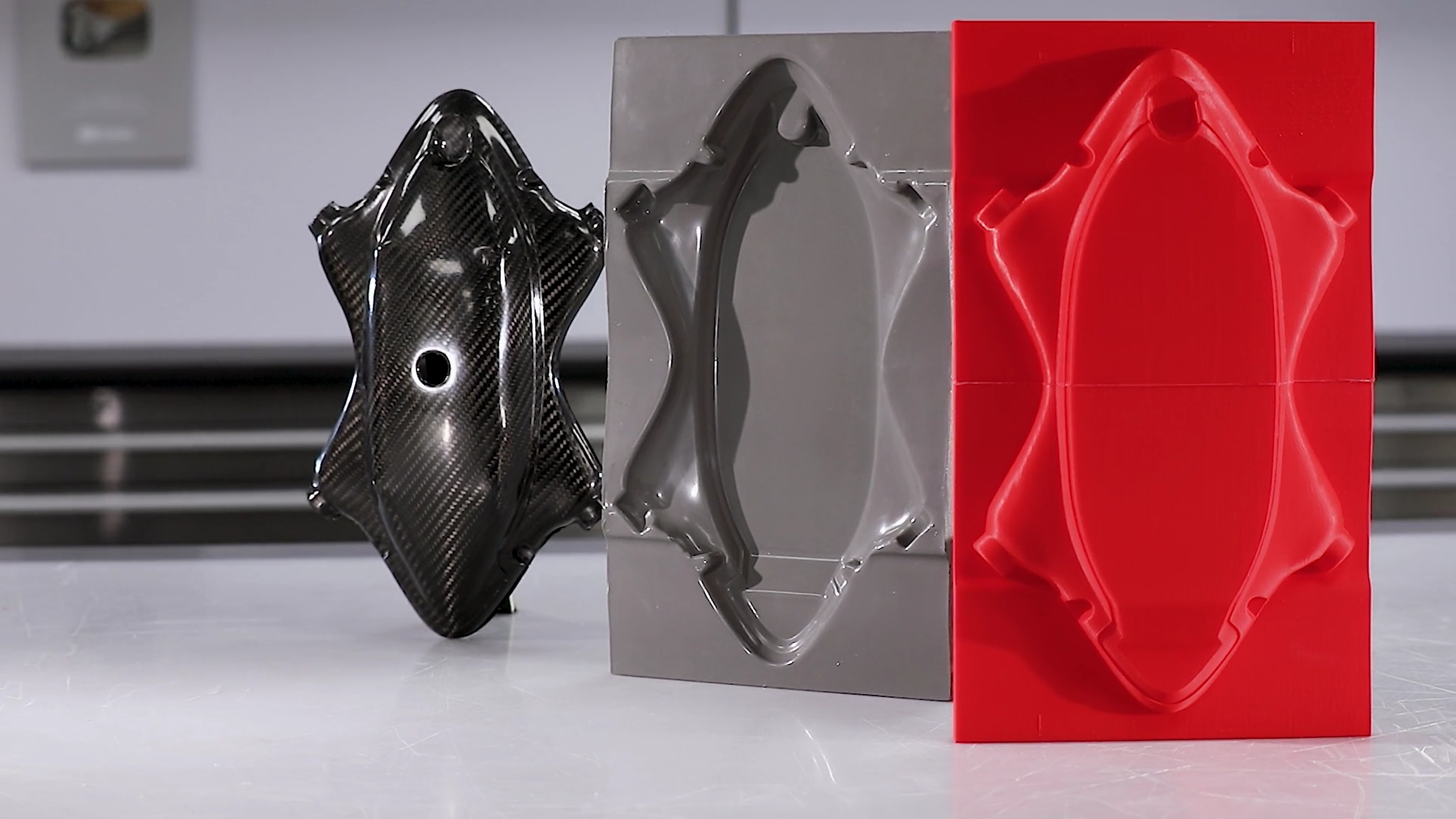
6. Separate the mold from the pattern and prepare
Once fully cured, the mold can be removed from the pattern. Removing any excess material from the perimeter will often help with the release—plastic wedges can be used to carefully separate the mold from the pattern.
In the case of this high temperature mold, we now need to complete a post-cure on the mold. This involves a steady ramp in temperature up to the service temperature to condition the mold—information on this cure profile can be found in the datasheet for the product. For ambient temperature use molds, this step is not normally necessary.
Prior to use, the mold is then coated with release agent in the same way as the pattern was coated.
2021 Edition
Professional 3D Printer Buyers Guide
Choosing the right 3D printer doesn’t have to be difficult. Find the perfect printer for your application. This in-depth guide covers pricing, materials, dimensional accuracy, and more.
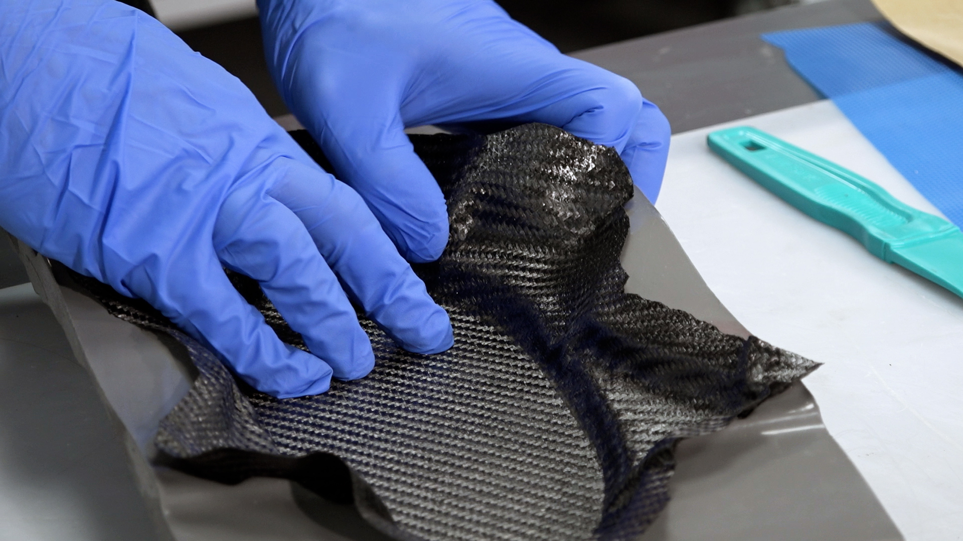
We chose to make the final component using an out-of-autoclave prepreg process, which requires a vacuum and oven.
These parts are to be made with an extremely thin (0.25mm) laminate, which consists of only one ply of 210g XC110 prepreg carbon. The actual handling of the prepreg is relatively simple, but great care must be taken to ensure the material is properly down in the mold. Work systematically from the center lowest point so that you do not end up bridging over any corners or detail.
Laminating tools, called dibbers, can be used here to help press the prepreg down into the mold. These tools can be made by hand, bought ready-made, or by using edges of other tools (e.g., the handle on shears). It is key to ensure there are no bridges or voids. Laying up other pieces around tight corners or detail may lead to creasing of the material or it lifting. In these areas, composite snips can be used to make small cuts to allow the material to lap and conform to the mold.
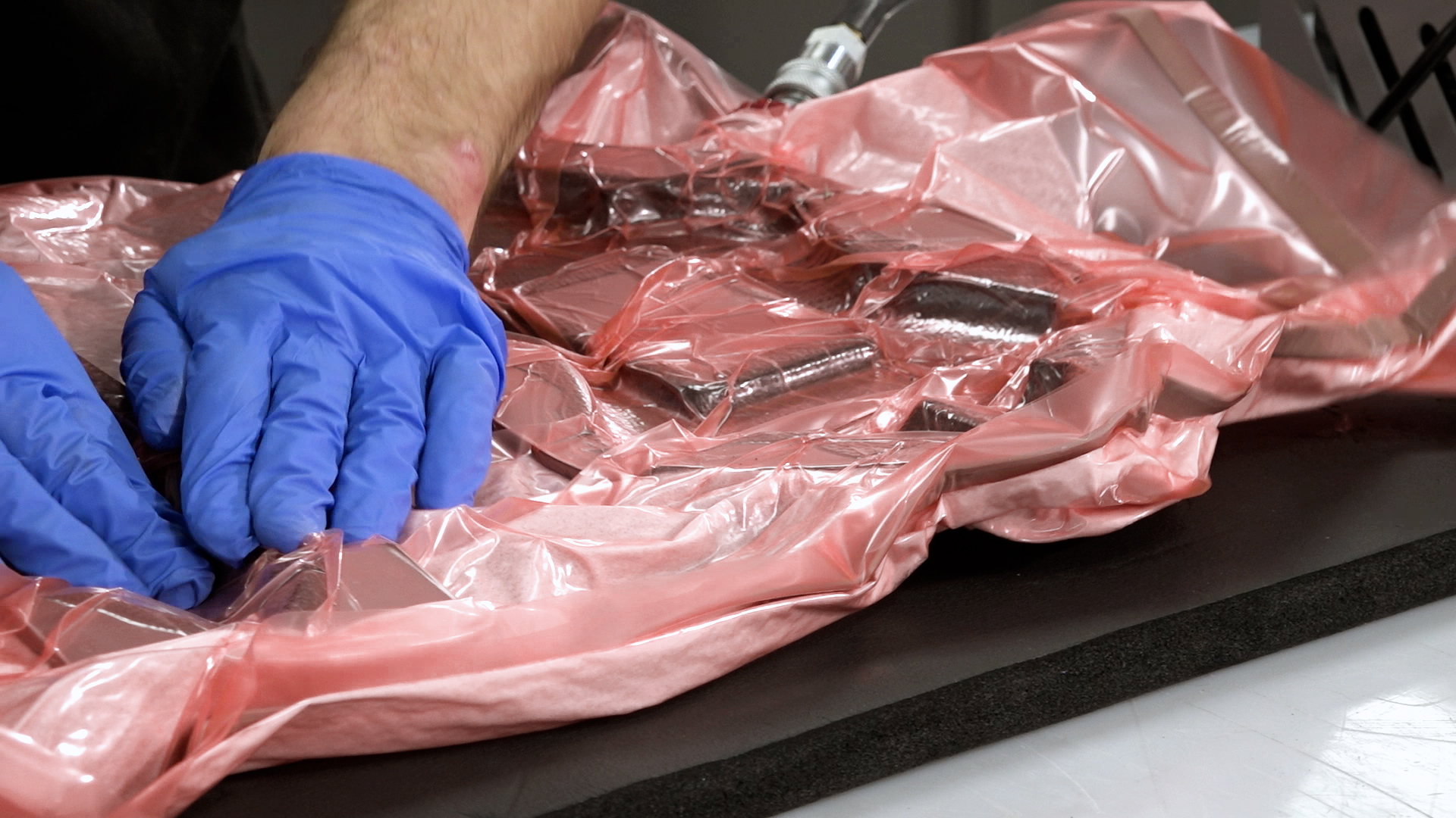
8. Vacuum bag the part
As these parts are only one ply thick, the typical de-bulking processes that are normally used in prepreg laminating are not required. Instead, the part can be put straight into the final vacuum bag ready for cure, which starts by applying a non-perforated release film to the prepreg. It is essential that this layer, just like the laminate itself, is carefully pressed onto the mold surface without any bridges. Once on the mold surface, rub with a cloth to press the release film firmly onto the material. You can use flash release tape to help hold the film in place if necessary.
For this size part, it is only required to have breather on the underside and edge of the part to provide an air path. Not having breather on the material surface actually helps on complex shapes as the breather does not get in the way of the vacuum bag getting into the tight corners and detail.
The bag being created is an envelope bag with the mold placed directly into the bag. This is common with production of smaller prepreg parts as it is possible to place several small parts into one big vacuum bag and cure them all together. The through bag connector is placed on one corner of the breather to ensure there is a continuous air path.
Start by pulling only a partial vacuum, stopping the pull as necessary to position and move the bagging film. This stage is critical to get the film into all the corners and recesses of the mold. Use creases of film to achieve this—as the vacuum increases, the spare film in the crease will be pulled into the corner, thus avoiding any bridging of the film. Once the bag is positioned correctly, a full vacuum can be pulled. Once a full vacuum is pulled, carry out a leak test for at least 10 minutes.
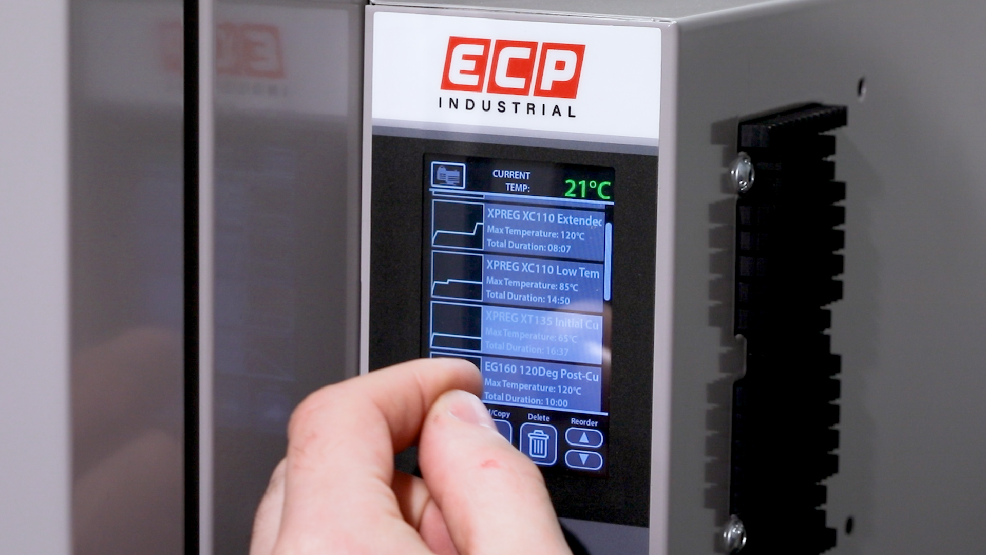
9. Oven cure the prepreg
With the bag pulled down and successfully leak tested, it can now be put in the oven to cure. Place the bag carefully in the oven, ensuring the bag cannot snag or catch on any edges, causing a puncture. Connect the vacuum line inside the oven and connect the pump to the assembly outside. You can now run the pump, allowing the bag to be maintained under full vacuum throughout the cure.
Close the oven doors, switch on the oven, and program the cycle you wish to use. Our OV301 oven has a simple touchscreen interface, allowing quick programming—all of our standard cure cycles are pre-programmed from the factory.
10. Demold the finished part
Once the oven curing cycle has completed, allow the part to fully cool to room temperature before demolding. Failure to do so can cause surface defects. Once cool, remove from the oven and remove the bagging film and breather. The release film should easily pull off. Using demolding wedges or other pointed items, taking care to avoid scratching the mold, carefully pry the edges of the part away from the mold. You may need to be systematically working around the mold to lift the part evenly until it comes free.
The demolded part then just needs trimming and finishing with a suitable rotary cutting tool and carbide abrasive tools and papers to give a nice, clean edge. The finished carbon fiber part can now be put into service.
Dynamism, a leader in 3D printing solutions, announced their expansion into Industry 4.0 software with the addition of Teton Simulation’s SmartSlice, a Cura Slicing Software plugin that uses cloud-based Finite Element Analysis to optimize print parameters in order to create parts that meet performance requirements while reducing printing times and material usage. “As a leading provider of 3D printing solutions, it is important that we provide end-to-end solutions for professionals”, CEO Douglas Krone said, “this includes 3D scanners, materials, coaching from 3D printing specialists, and now software.”
Why businesses need Smart Slice – Less iterations, faster prints, and material savings.
When a part is 3D printed, there is a large amount of uncertainty in knowing if the part will perform as intended under end-use conditions. This leads to numerous build and break iterations resulting in excessive print times and wasted material. At the end of the day, this iterative process degrades two of the key advantages of 3D printing: reduced lead times and reduced waste. Combined with 3D printing’s recent massive growth in end-use applications, Smart Slice is poised to become an important solution for businesses wanting to increase their bottom line through applied 3D printing.
“Our SmartSlice technology was built from the ground up to give 3D printer operators near instant feedback on the viability of their project. There is simply no other solution in the industry that can provide lightning-fast, accurate feedback on the ‘as printed’ state of a part. Plus, our optimization feature takes the guesswork out of determining the right slicing parameters. We do all the work, so the user doesn’t have to. All of this capability is provided within the slicer making it very easy to use.” says Mike Kmetz – CEO at Teton Simulation Software.
Who Can Benefit?
If you are using 3D printing for end-use parts, jigs and fixtures, concept validation, and/or manufacturing, SmartSlice’s part optimization is for you. Benefits are measured in days, material costs, and valuable engineering time both from failed iterations and straight print times for production parts. For example, in a test 3D printing a production run of 50 moderately sized levers, SmartSlice’s optimization was able to save 3.15 days in total print time per run while saving nearly 1kg of filament, all while delivering a part that met its performance requirements. For users unable to utilize cloud-based functionality due to IT limitations, local options are also available.
Multiple optimization parameters allow end-users to ensure their part meets requirements, ending the build, break, iterate cycle inherent in mechanical 3D Printing.
Watch the Webinar
View our recorded webinar from March 11th, 2021 including a live demonstration of the software features and BASF case studies.
“Teton's Smart Slice plugin brings engineering grade part simulation to Ultimaker Cura users. Using the integration options of our open and pluggable platform it will make sure parts still meet their engineering criteria, but need less material and therefore saving valuable time and costs. The cooperation with Teton and the integration of their innovative solution are a prime example of how we will be continuously adding value for our professional customers.” Paul Heijmans – Senior VP Software at Ultimaker.
Designed for maximum output and minimum waste, Fuse 1+ 30W is a compact SLS 3D printer that packs an industrial punch. Unlock unprecedented print speeds, a full range of materials, and a convenient, intuitive workflow to deliver truly rapid prototyping and production in-house.
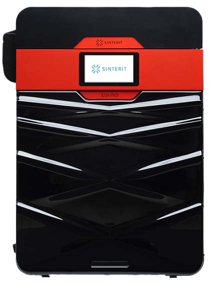
Sinterit Lisa Pro
Another one of the market’s most affordable SLS options, the Lisa Pro provides a wider range of materials but at the cost of max 3.5″ (PA12/11) and 4.3″ (TPE/TPU) build volume in one direction and more involved workflow.
The Basics
Formlabs Fuse 1+30W
Sinterit Lisa Pro
USA
Country Designed In
Poland
165 x 165 x 300 mm 6.5 x 6.5 x 11.8 in
Build Volume
Length x Width x Height
PA: 90 x 130 x 230 mm TPE/TPU: 110 x 150 x 245 mm
Nylon 12 / Nylon 11 /
Nylon 12 GF (glass-filled) /
Nylon 11 CF (carbon-filled) /
TPU*
Available Materials *More materials to come.
Nylon / TPE / TPU
$100+/kg
Material Price
$140+/kg
20 – 50 %
Material Refresh Rate
Amount of new powder added with reclaimed powder every cycle.
20 – 50 %
< 60 minutes
Warmup Time
Time it takes for the build volume to head up before printing begins.
60-90 minutes
1-2 hours
Cooldown Time
1+ hours
110 µm
Minimum Layer Height
75 µm
Ethernet, Wifi, USB
Connectivity
Ethernet, Wifi, USB
$24,999 ~ $40,000 for the complete workflow package
Starting Price
$18,990 ~ $40,000 for the complete workflow package
The Fuse 1+30W and Sift provide an easy-to-use, end-to-end solution for medium-large single parts or short-run production. A 6.5 x 6.5 x 11.8″ build volume enables users to pack a lot of parts in a small volume. The enclosed system with transferrable build chamber and combined cleaning/sifting/mixing station provides a seamless and clean workflow. In addition, a second build volume can be added to your rotation for minimal downtime between prints.
Lisa Pro
The Lisa Pro provides an affordable SLS 3D printing solution with wider range of materials, but with a few sacrifices. First, a maximum 3.5″ build volume in one direction when printing Nylons, a material used in SLS, limits the printer to smaller objects and smaller production runs. Next, a more involved workflow will have you transferring, scooping, measuring, pouring, and brushing volatile powders in open-air environments at several points in the process.
Materials
Out of the gate, the Fuse 1+30W only prints a customized PA12, with more materials in development. That said, PA12 accounts for 90-95% of all SLS printing and has exceptional material properties. This includes biocompatibility, great heat deflection, and resistance to UV, moisture, and solvents.
The Lisa Pro is equipped with an optional nitrogen filled chamber, which helps to print their wider range of materials. Material options includes PA11, PA12, and TPE/TPUs in varying colors.
Choosing the right 3D printer doesn’t have to be difficult. Find the perfect printer for your application. This in-depth guide covers pricing, materials, dimensional accuracy, and more.
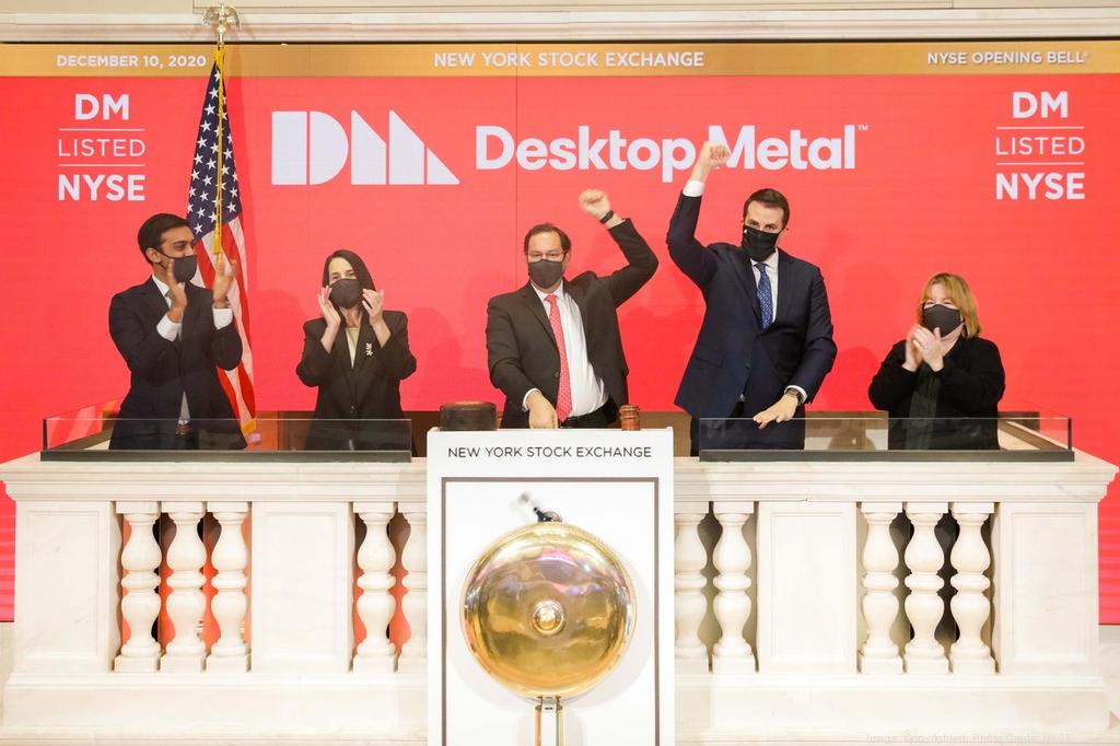
Announced today, two 3D printing powerhouses are to join forces with a definitive agreement for Desktop Metal to acquire EnvisionTEC, a market leader in photopolymer printing with an incredible IP and product portfolio. The acquisition will add a large portfolio of photopolymer 3D printers for end-use parts, dental and orthodontic applications, bioprinting, and casting markets such as jewelry. Dynamism is an authorized reseller of both brands, discover their available 3D printing solutions here.
In the industrial additive manufacturing market, growth has been driven by a shift from purely prototyping to dedicated solutions for end-use applications, an area where EnvisionTEC excels. Founded in 2002, EnvisionTEC boasts a large portfolio of over 190 materials and seven current 3D printers, which come in a variety of industry-focused configurations. Of notable mention, a recent material addition, EnvisionTEC’s E-3955 Thermal Cure exceeds material properties of Ultem1010, the strongest material currently available for material extrusion 3D printers (FFF/FDM). In addition, the EnvisionTEC portfolio includes a massive, high-speed 3D printer powered by an 8k DLP light source, printers 100X faster than legacy thermoplastic printers, a bioprinter, and several industry leading solutions for dental, jewelry, and manufacturing applications.
A complete look at the combined Desktop Metal and EnvisionTEC hardware portfolio
Through the acquisition expect “business as usual” for both companies. EnvisionTEC will continue as a wholly-owned subsidiary, maintaining the current organizational structure, with founder Al Siblani remaining as CEO, and the EnvisionTEC sales organization and channel program remaining in place.
Dynamism is an authorized reseller of both Desktop Metal and EnvisionTEC
Discover solutions from each company by clicking the logos below or reach out to sales@dynamism.com with your additive needs. Our dedicated industrial 3D printing specialist can work with you to discover how these complementary product lines can help your company with the digital manufacturing transformation.
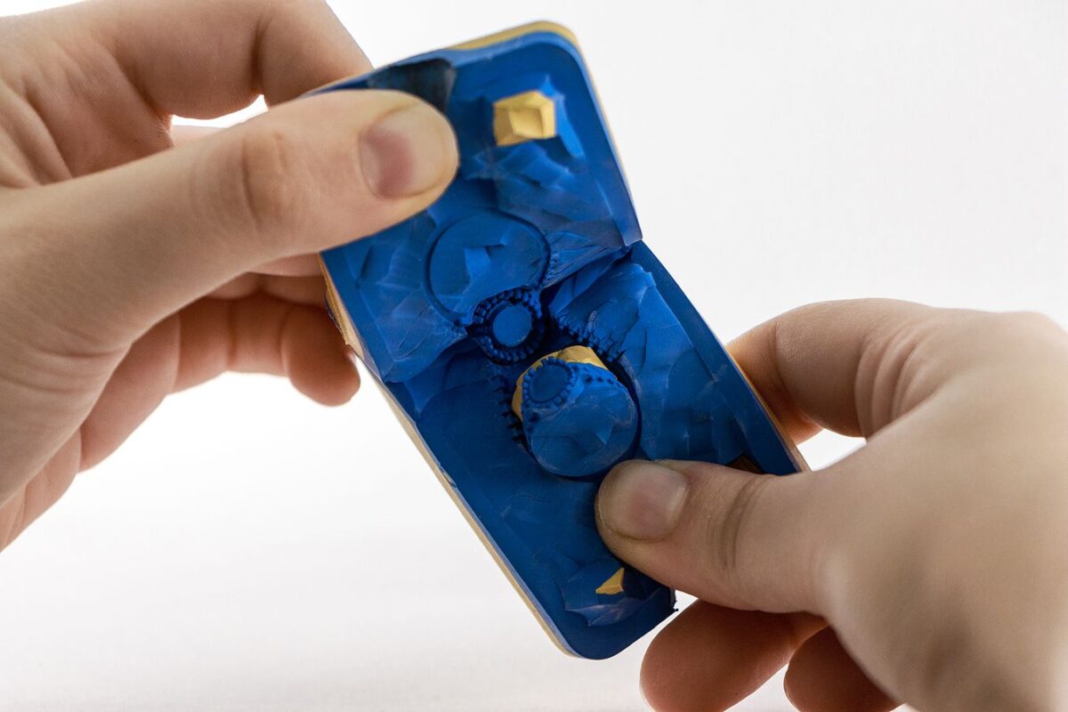
Rubber molds are used to produce wax models in quantity for investment casting of metal parts such as jewelry, small industrial components, and gaming miniatures. 3D printed masters are cheaper, faster, and more accurate than hand-crafted designs. In this white paper you’ll learn:
How 3D printing can be used for casting small metal parts
What vulcanization is and how rubber molds are made
Material compatibilities for rubber mold-making
How to select the right resin for your rubber mold-making process
When you begin researching 3D printers one question often comes to mind: “What is the resolution of this 3D printer?” This is not an easy question to answer and has certainly led to failed expectations for the unsuspecting. So, before you let ‘resolution’ sway your next 3D printer purchase, let’s take a moment to define 3D printer resolution and some common misconceptions of the metric.
Just because a 3D printer data-sheet boasts a 1.25μ X/Y/Z resolution does not mean you can expect this from the finished part, nor does it guarantee a smooth surface finish.
What Is 3D Printing Resolution? It’s Not What You May Think.
Due to a lack of metric standardization in additive manufacturing, 3D printer resolution can go by a number of names including X/Y/Z resolution, positioning resolution, or theoretical resolution. In theory, this metric is a measurement of the smallest movement a 3D printer can achieve in each direction. Set by hardware and firmware, positional resolution is calculated by the number of ‘steps’ in a 360° rotation. These micro rotational movements are delivered by stepper motors and belts to drive the X, Y, and Z axes. The more steps, the finer movements a 3D printer can achieve. While this is important, manufacturers often provide a theoretical metric, unrealized by the user due to a number of factors including material shrinkage, belt tensioning, nozzle size, and more.
What You’re Probably Looking For…
For people new to 3D printing and even some tenured professionals, resolution is often misconstrued for one of two things, dimensional accuracy of the printed part and/or surface finish. These are both complex topics so let’s take a moment to analyze each. Keep in mind there are pros and cons to each 3D printing technology so this article should only be part of your overall assessment. If you need help, Dynamism’s 3D printing specialists are here to help.
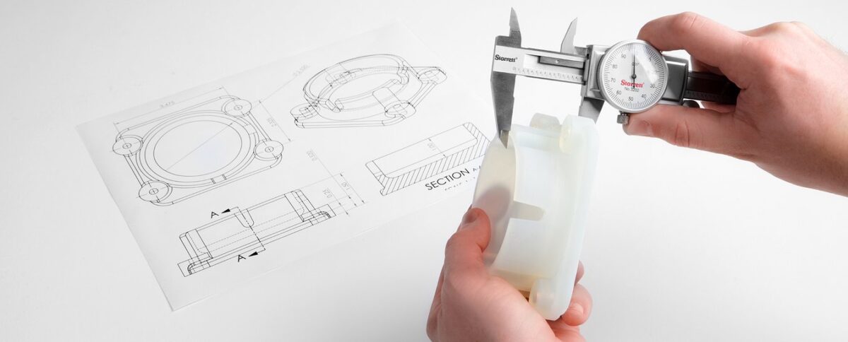
Printed Part Dimensional Accuracy
Printed part dimensional accuracy is not solely defined by hardware. Instead, there are a number of influencing factors for each of the 3D printing technologies. Below, we break down influencing factors for two of the most common technologies.
Material Extrusion 3D Printers
For material extrusion 3D printers, the dimensions of your final part are influenced by positional resolution, nozzle size, die swell, belt tensioning, and shrink rate of the material. Material is a huge contributing factor here. Some materials have more die swell than others. Additionally, Styrene-based materials, like ABS, have high shrink rates which can result in parts smaller than intended. Thankfully, smaller nozzles can be added to most FFF 3D printers to achieve more accurate prints and smoother surface finishes but as a tradeoff, prints take longer to finish.
Resin 3D Printers
For stereolithography aka resin printers, dimensional accuracy is mainly determined by the material and laser spot size, or screen resolution for DLP 3D Printers. Some materials will shrink when undergoing the heat and UV curing process. Overall, SLA and DLP printers produce more accurate parts than material extrusion printers but as a tradeoff, most affordable market options have smaller build volumes and materials only emulate end-use materials, like ABS, Polycarbonates, and Polyamides. Exceptions do exist for build volume, like the Formlabs Form 3L and Nexa’s super fast NXE400.
Surface Finish
When looking for a smooth surface finish, SLA/DLP 3D printers provide exceptionally smooth finished prints. As mentioned above, the technology does come with some tradeoffs. For material extrusion printers, smoother surface finishes can be achieved with smaller nozzles and finer layers. Furthermore, some materials can be vapor smoothed, providing a surface finish that nears that of resin 3D printers.
Now That We’ve Settled That…
As you continue your 3D printer shopping journey, do not let 3D printer resolution sway your decision, as this metric is often theoretical and limited by other factors such as materials. If you need help selecting the right 3D printer, Dynamism’s 3D printing specialists are here to help. With a brand agnostic approach and large selection of technologies and brands, our goal is to get you the best possible solution for your application.
Renowned for their ease of use, large material selection, and seamless network connected workflow, Ultimaker defines professional desktop 3D printing. Get a side-by-side comparison of the Ultimaker 2+ Connect, S3, and S5 3D printers including:
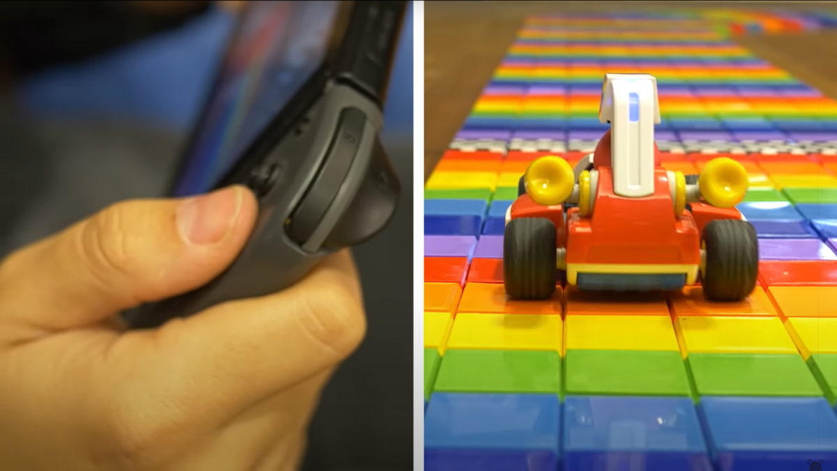
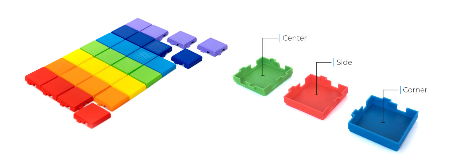
September 3rd, 2020 marked 35 years since Super Mario Bros’ first launched. To celebrate, Nintendo announced an innovative new augmented reality version of the beloved Mario Kart series, Mario Kart Live: Home Circuit. Utilizing a camera-equipped Kart synced to a Nintendo Switch, the game puts you directly in the driver’s seat, navigating whatever course you can devise around the home. The innovative game format has given rise to some pretty insane courses. One of notable mention, a 3D printed recreation of the classic SNES Rainbow Road course, more information below.
Created by Additive Manufacturing Specialist, Antonio Aranzana and a fleet of BCN3D 3D Printers, the roughly 17′ by 18′ course is comprised of 4,434 PLA pieces. The course was completed in just three short days on BCN3D’s new Sigma D25. A feat hard to match with other 3D printers, made possible by their innovative Independent Dual Extruder (IDEX) technology. The IDEX system utilizes two, independent extruders to offer mirror and duplication printing modes, cutting the production time to half that of other single head 3D printers.
Designed for a 0.6mm nozzle, each tile can be printed in 9 minutes. Visit Thingiverse to find the design.
While creating a Mario Kart track may be fun and games, BCN3D’s IDEX system points to a growing trend as additive manufacturing transitions from simple prototyping to low-volume production, mass customization, and end-use parts. Click the button below to learn more about BCN3D’s 3D Printers.
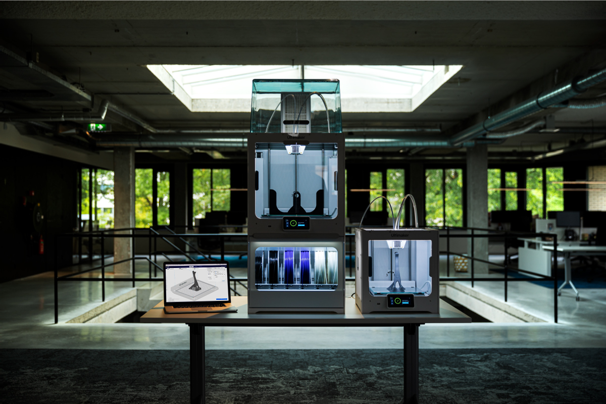
Maintaining an inventory of indirect machine materials associated with manufacturing and production can be essential to business continuity. Insert the “Take One, Make One” (TOMO) model, a new style of inventory management that leverages additive manufacturing and a digitized inventory of high wear-and-tear items to reduce physical inventory and machine downtime while streamlining parts supply.
Created by Azoth, a Dynamism customer and a member of the EWIE Group of Companies (EGC), TOMO transforms physical inventory into digital inventory that can be manufactured on-demand using 3D printing. Every time a replacement part is pulled from physical inventory and deployed for use, another is printed and stored for the next time that part needs to be replaced. The result: critical machine spare parts that traditionally would have taken six to twelve weeks to replace are able to be manufactured in hours or days.
I’ve seen processes that can have a hundred parts ready for you quicker than some companies can cut a purchase order, send it to their suppliers, and receive back into their system.
– Cody Cochran, General Manager of Azoth.
What parts are great candidates for the TOMO model? So far jigs and fixtures, gripper fingers, blow-off nozzles, and gage handlers have made ideal parts for moving to a digital inventory, although this is just the start. The TOMO model has much to be explored. Like traditional manufacturing tools, each 3D printing technology has unique traits, strengths, and weaknesses that make it ideal for different applications. Understanding additive manufacturing technologies and part requirements is one of the most significant hurdles to implementing TOMO. This is where Dynamism comes in, with a large selection and deep understanding of the various additive manufacturing technologies. For help selecting the right 3D printing technology, contact us here.