Choosing between Bambu Lab vs Prusa has become the defining decision for anyone entering the desktop 3D printing market in 2026.
Bambu Lab vs Prusa: The Two Titans of Desktop 3D Printing
Choosing between Bambu Lab vs Prusa has become the defining decision for anyone entering the desktop 3D printing market in 2026.
Both manufacturers have earned devoted followings, but for distinctly different reasons. Prusa built its reputation on open-source principles, meticulous engineering, and bulletproof reliability over more than a decade. Bambu Lab disrupted the industry in 2022 with aggressive pricing, impressive speeds, and a closed ecosystem that prioritizes user experience over tinkering and in 2026, they’ve continued to push the value story even further.
For educators building maker labs, small business owners scaling production, and prosumers demanding consistent results, understanding these differences matters. The right choice depends less on which printer is “better” and more on which philosophy aligns with your workflow, technical comfort level, and long-term goals.
This Bambu Lab vs Prusa comparison examines both brands across the metrics that matter most: print quality, speed, reliability, ease of use, material compatibility, and overall value. We focus primarily on the Bambu Lab P1S and X2D against the Prusa MK4S and XL, the sweet spot for serious users who need production-ready performance without industrial-grade budgets.
Quick Comparison: Bambu Lab vs Prusa at a Glance
| Feature | Bambu Lab P1S | Bambu Lab X2D | Prusa MK4 | Prusa XL |
|---|---|---|---|---|
| Price | $549 | $649 / $899 combo | $999 assembled / $709 kit | $2,299 / $4,499 assebled 5 tool head |
| Print Speed | 250-300mm/s | 250-300mm/s | Up to 200mm/s | 100-150mm/s |
| Build Volume | 256×256×256mm | 256×256×256mm | 250×210×220mm | 360×360×360mm |
| Enclosure | Yes | Yes, actively heated to 65°C | Optional | Optional |
| Multi-Material | AMS (up to 4) | AMS (up to 25 colors) | MMU3 (up to 5) | Up to 5 toolheads |
| Open Filament | Partial | Partial | Yes | Yes |
| Open Source | No | No | Yes | Yes |
| Best For | Prosumers, business | Advanced, dual nozzle | Educators, tinkerers | Large format, education |
Print Quality and Speed: Different Approaches to Excellence
When it comes to the Bambu Lab vs Prusa decision, the right choice depends on your specific workflow and priorities. Both manufacturers deliver exceptional print quality, but they achieve it through contrasting engineering philosophies.
Prusa’s approach emphasizes mechanical precision and proven technology. The MK4S the 2025 evolution of their flagship MK4 features a refined 360° cooling system, a high-flow Nextruder, and numerous firmware optimizations that deliver faster speeds without sacrificing accuracy. Independent tests gave the MK4S a perfect 30/30 score for print quality from TechRadar, and CNET named it “The Best Printer for Quality.” Prints emerge with smooth surfaces, accurate dimensions, and predictable results across various geometries.
Bambu Lab prioritizes speed without sacrificing quality. The P1S and X2D utilize CoreXY motion systems, sophisticated vibration compensation, and AI-powered flow calibration to achieve print speeds of 250–300mm/s routinely. A benchy that takes over 40 minutes on the MK4S finishes in under 20 minutes on the P1S with comparable surface quality. The difference becomes stark for production runs or classroom environments where throughput matters.
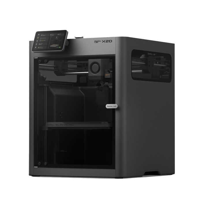
The X2D takes this further with a dual nozzle system, a direct drive main nozzle for precision and a Bowden auxiliary nozzle for support and multi-material work. Combined with 31 sensors, a toolhead camera for AI print monitoring, and an actively heated chamber reaching 65°C, the X2D is Bambu’s most capable machine to date.
For absolute detail on miniatures or small-scale prototypes, both perform admirably at slower speeds. Prusa’s open-source slicer gives advanced users granular control over acceleration and jerk settings. Bambu’s proprietary Bambu Studio applies machine learning to optimize paths automatically, brilliant for most scenarios but offering less manual override for edge cases.
Bambu Lab prints 2-3x faster with comparable quality. Prusa’s MK4S delivers exceptional accuracy and has earned top marks from independent reviewers. For production environments, Bambu’s speed advantage compounds significantly over time.
Reliability and Maintenance: Open vs. Closed Ecosystems
Reliability means different things depending on your technical capabilities and support infrastructure.
Prusa has earned near-legendary status for reliability. The MK4S builds on years of field-tested engineering with fully documented components, transparent firmware, and a massive community knowledge base. Prusa ships around 10,000 printers per month and reports a claim rate of less than 1%. When something breaks and everything eventually breaks replacement parts are readily available, often from third-party suppliers. For schools and small businesses without dedicated technical staff, knowing you can diagnose and fix issues with community documentation provides immense peace of mind.
Bambu Lab printers are engineered for reliability through tight integration rather than user serviceability. The closed ecosystem means fewer variables, and quality control has proven solid across multiple product generations. The X2D adds 31 sensors including filament runout, grinding, and tangle detection, proactive monitoring that catches issues before they become failed prints. However, when issues do arise, you are dependent on Bambu’s support infrastructure and proprietary parts. For institutions requiring guaranteed uptime, this is a legitimate consideration.
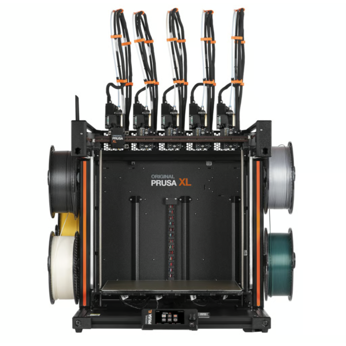
Both manufacturers offer multi-material systems Prusa’s MMU3 (up to 5 colors) and Bambu’s AMS. Bambu’s AMS implementation on the X2D supports up to 25 colors with faster purges and better waste management than the previous generation. The Prusa XL takes a different approach entirely with true independent toolheads up to 5 allowing near-zero-waste multi-material printing without purge towers.
Prusa is easier to repair and has stronger community support. Bambu requires less frequent maintenance but creates more manufacturer dependency when issues arise. The X2D’s 31-sensor system catches problems proactively.
Materials, Ecosystem, and Long-Term Value
Material compatibility reveals each manufacturer’s strategic priorities.
Prusa maintains an open-filament philosophy. The MK4S handles PLA, PETG, ASA, PC, flex, and more with published profiles. You can use any filament from any manufacturer without restriction, which significantly reduces operating costs and eliminates vendor lock-in. Prusa’s open-source PrusaSlicer includes over 180 tested material profiles.
Bambu Lab technically supports third-party filaments, but the ecosystem strongly encourages Bambu-branded materials. RFID tags auto-configure settings, and Bambu Studio’s profiles are optimized for their filaments. For high-temperature engineering polymers, the X2D’s actively heated chamber reaching 65°C and support for PC, nylon, and carbon-fiber composites through the main nozzle provide genuine advantages.
The pricing story in 2026 has shifted dramatically in Bambu’s favor. The Prusa MK4S assembled now retails at $925 while the Bambu P1S starts at $549 and the flagship X2D at $649. Even the Prusa XL, which received a 2026 price drop, sits at $2,299 for the single toolhead setup. Bambu is delivering comparable or faster print quality at significantly lower entry points. For buyers weighing value per dollar, the math has changed.
However, total cost of ownership tells a more complete story. Prusa’s open filament ecosystem typically yields lower per-kilogram material costs. Bambu’s faster print speeds reduce electricity costs and increase throughput value. For educational institutions, Prusa’s open-source curriculum resources and established educator community provide significant intangible value. For small businesses focused on production efficiency, Bambu’s combination of speed and price is increasingly difficult to argue against.
Bambu Lab’s 2026 pricing makes it one of the strongest value propositions in desktop 3D printing. Prusa’s open filament ecosystem reduces long-term material costs and the XL’s true multi-material toolchanger remains unmatched for zero-waste multi-color work.
Which Printer Matches Your Needs?
Choose Prusa if you:
- Value open-source principles and long-term repairability
- Need comprehensive community support and documentation
- Prefer vendor-neutral filament sourcing
- Operate in educational settings emphasizing learning over production
- Need zero-waste multi-material printing (Prusa XL)
- Have technical users comfortable with maintenance and troubleshooting
Choose Bambu Lab if you:
- Prioritize print speed and production throughput
- Want minimal setup and excellent out-of-box experience
- Need multi-color printing up to 25 colors (X2D with AMS)
- Need dual nozzle capability for complex multi-material work (X2D)
- Want reliable performance with limited technical expertise on staff
- Are working within a tighter budget, Bambu offers more speed per dollar in 2026
Frequently Asked Questions
Neither is objectively better, they serve different users. Bambu Lab is better for speed, ease of use, and production throughput. Prusa is better for repairability, open-source flexibility, and educational environments. The right choice depends entirely on your priorities.
Yes, but with limitations. Bambu Lab printers technically support third-party filaments but the ecosystem is optimized for Bambu-branded materials with RFID auto-configuration. Custom profiles can be created but require additional setup and experimentation.
Both are reliable but in different ways. Prusa has a longer track record, fully documented components, and superior community support for self-repair. Bambu Lab has fewer maintenance issues out of the box but is more dependent on manufacturer support when problems arise.
Prusa is beginner-friendly with excellent documentation and community support, though it requires more hands-on involvement than Bambu Lab. For users who want a true plug-and-play experience, Bambu Lab offers a more streamlined out-of-box setup.
Prusa is generally preferred for educational settings due to its open-source curriculum resources, repairability, vendor-neutral filament compatibility, and strong community. However, Bambu Lab’s ease of use and significantly lower price point in 2026 make it increasingly popular in classrooms focused on design output and throughput rather than printer maintenance and tinkering. Prusa is beginner-friendly with excellent documentation and community support, though it requires more hands-on involvement than Bambu Lab. For users who want a true plug-and-play experience, Bambu Lab offers a more streamlined out-of-box setup.
The Bambu Lab X2D is Bambu’s current flagship desktop 3D printer, featuring a dual nozzle system (direct drive main + Bowden auxiliary), an actively heated chamber up to 65°C, 31 sensors including AI print monitoring via a toolhead camera, and AMS support for up to 25 colors. It starts at $649 for the printer or $899 as a combo with the AMS.
READY TO DECIDE?
Dynamism carries the complete range of Bambu Lab and Prusa 3D printers, filaments, and accessories. Our team has hands-on experience with both ecosystems and can help match the right platform to your workflow, budget, and use case.
Shop Bambu Lab
Shop Prusa
Talk to a specialist: sales@dynamism.com | 1-800-711-6277