The Ultimaker 2+ Connect comes in reusable, durable packaging, specially designed to protect your 3D printer. Ensure you save your packaging, it will be required to send the machine in should it require warranty service and will ensure the safety of your machine when changing locations.
Follow the steps below to unpack your Ultimaker 2+ Connect:
01
Place the box on the ground.
02
Remove the plastic locking clips from the lower section of the box.
03
Holding the handles, lift the upper section of the box, and place it aside.
04
Take the quick start guide, safety and warranty information booklet, accessory box, and a spool of filament off the upper cardboard piece.
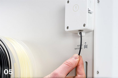
05
Remove the upper cardboard section and four foam pieces.
06
Carefully lift the Ultimaker 2+ Connect out of the bottom cardboard section and foam pieces.
07
Place the printer on a flat surface.
What Is Included With Your Printer
The Ultimaker 2+ Connect is supplied with several hardware accessories. Check if all these items are included before continuing:
Accessories
- Glass plate
- Spool holder
- Power adapter and cable
- Ethernet cable
- USB stick
- Calibration card
- 0.4 mm nozzle
Consumables
- PLA Silver Metallic 750 g
- Glue stick
- Oil
- Grease
Tools
- Hex screwdriver 2 mm
- Hex key 2.5 mm
- Nozzle wrench
- Print head calibration aid
Documents
- Quick start guide
- Safety and warranty information
Get to Know Your Printer
Familiarize yourself with the different components of the Ultimaker 2+ Connect. Throughout our documentation, these terms will be used frequently.

Hardware Installation and Setup
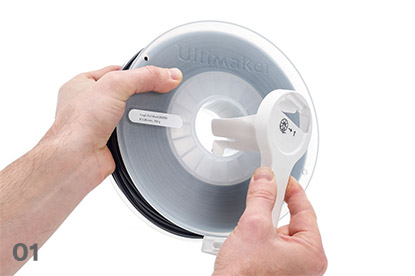
01
Insert the spool holder into the back panel and push until it snaps into place.

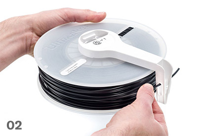
02
Open the front build plate clamps to insert the glass plate.

03
Slide the glass plate into the rear build plate clamps, then close the front clamps.

04
Connect the power cable to the printer with the flat side facing down and the other end to a power outlet.