Categories
Engineering Manufacturing

Yasuhide Yokoi and Final Aim Inc’s Autonomous Delivery Robot

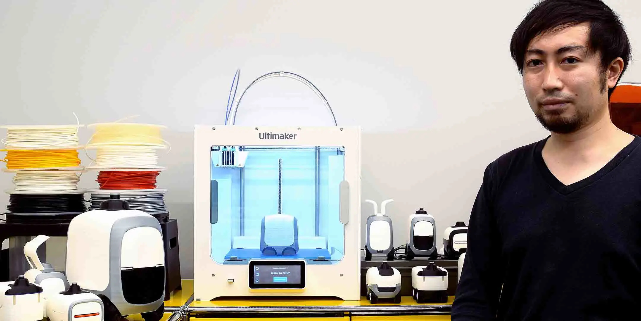
Yasuhide “Yasu” Yokoi is the cofounder of design and technology firm Final Aim Inc., which works with laboratories, startups, and multinational companies to transform ideas into tangible solutions. There, he and his team use Ultimaker 3D printers to better enable rapid design iterations during the prototyping phase.

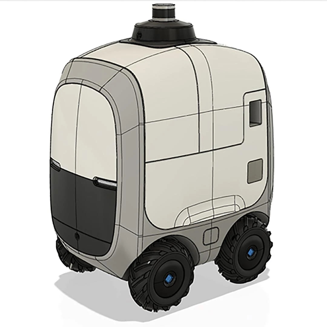
One of the company’s latest projects is the OSTAW Camello, an autonomous package delivery robot.

Revolutionizing Package Delivery

The Camello was designed to address issues in the delivery logistics chain in Singapore, which causes high shipment costs and operational complexities. Due to low loads and long waiting periods in loading and unloading bays, package deliveries are often inefficient – a fact exacerbated by high delivery volumes and tight delivery deadlines.

To tackle this challenge, Final Aim collaborated with a Singaporean robotics start-up OTSAW Digital PTE LTD, with the Camello being the final product.

The Camello is user friendly, featuring an ergonomic cargo space and sleek design – optimal for Singapore’s urban environment. Plans are currently underway for it to be used by various industrial key players, delivery companies, and retailers throughout Singapore, creating an improved ecosystem that provides smooth and efficient delivery to customers, while increasing profit margins for those businesses that use it.

The Birth of the Camello

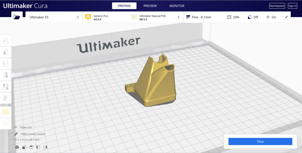
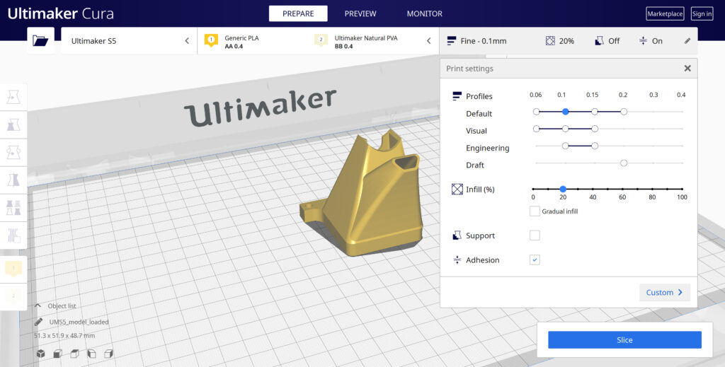
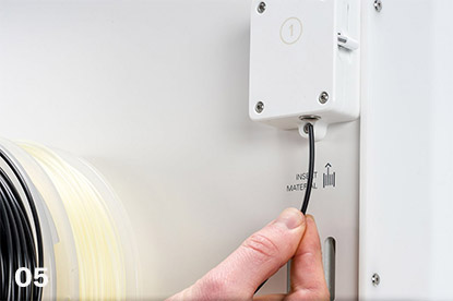
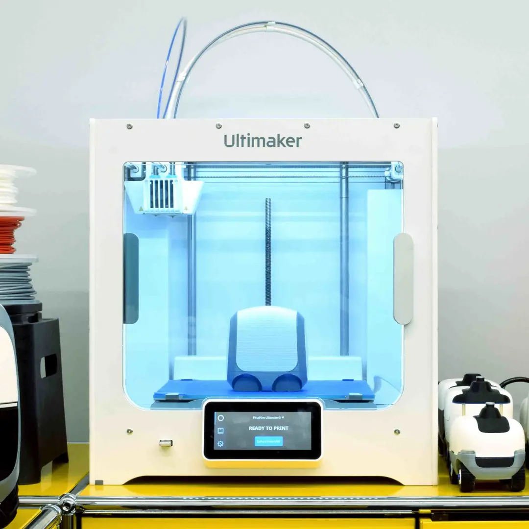
As with any product, several phases were involved in Camello’s design, with the Ultimaker S3, Ultimaker Cura, and CAD software acting as Yasu’s and Final Aim’s greatest companions throughout the process.

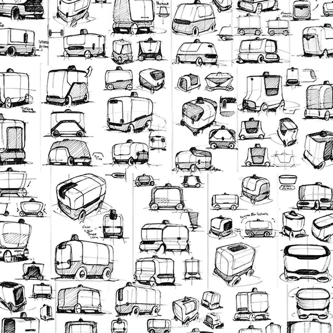
First came the robot’s concept development and evaluation. From the initiation to ideation, he used both hand-drawn design sketches and CAD software.

Image
Industrial designer Yasuhide Yokoi with the Ultimaker S3 and Camello prototypes

Once he developed the idea, Yasu began the process of presenting it to the higher-level management, frontline members, and end-users. This divergent approach allowed Yasu to gain as much feedback as possible, which he could then use to refine, improve, and further flesh out his concept.

Image
Early sketches of design ideas
Image
A CAD design iteration, which can be 3D printed

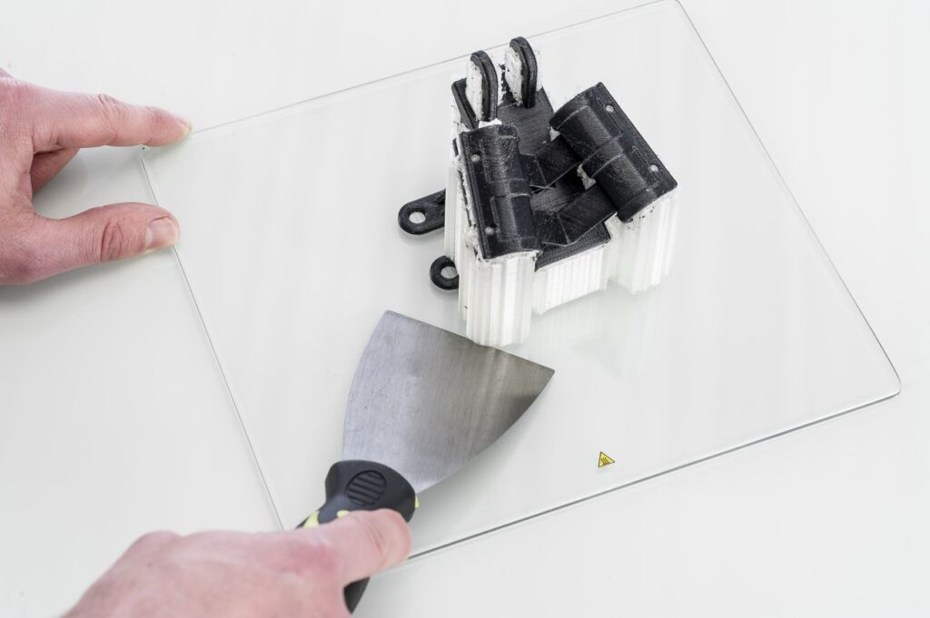
Next came the prototyping phase. As Yasu now had numerous potential ideas, he needed to rapidly actualize them – often on tight deadlines. Luckily, this was a task that 3D printing was able to easily handle. Compared to other common prototyping methods such as sculpting or carving from Styrofoam, chemical wood, or industrial clay, 3D printing is much more efficient – freeing up time for Yasu to work on other design tasks.

“More than just cost-cutting, 3D printing has added value to my process,” Yasu said.

Image
3D printed iterations of the robot, ready to be tested and compared

Finalizing an Intuitive Design

Yasu was also responsible for ensuring that the Camello’s final design was of excellent quality. As his works often incorporate organically curved surfaces and silhouettes, which are often difficult to implement, he needed to create numerous iterations. 3D printing technology utilizes the contour layers of printouts to analyze the curvature of surfaces – essentially an equivalent to the zebra mapping that CAD software performs.

“The Ultimaker S3’s double extrusion feature has [also] been essential to my everyday design applications,” Yasu said. “Together with Breakaway and PVA material, my printing experience has become exponentially more efficient. I am deeply satisfied with the resulting quality as it leaves behind no support structure remaining.”

Image
Final design iteration prototyped on the Ultimaker S3
Image
Production Camello delivering groceries in Singapore

For the Camello to be a success, its design had to be intuitive and accessible at first glance. The design process, therefore, involved divergent ideation, exploring all possibilities, which were then carefully narrowed in focus. Development speed was also critical for stakeholders’ requests.

3D printing enabled these stakeholders to see and touch a physical product, deepening their understanding of the Camello’s concept and design – and streamlining the decision-making process.

Image

Go To Market Faster

Discover how 3D printing can accelerate your development cycles, with insights including:

  • How to 3D print faster to test more iterations
  • 4 essential applications for designers
  • The ideal design studio setup and workflow
  • And lots more handy tips and tricks!
Categories
3D Printing

Ultimaker Support Resources

Categories
3D Printing

Ultimaker S3 / S5 Unboxing and Setup

The Ultimaker S3 and S5 come in reusable, durable packaging, specially designed to protect your 3D printer. Ensure you save your packaging, it will be required to send the machine in should it require warranty service and will ensure the safety of your machine when changing locations.


Follow the steps below to unpack your Ultimaker S3 / S5:


What Is Included With Your Printer

Accessories
  • Glass build plate
  • Spool holder with material guide
  • Power cable
  • Ethernet cable
  • USB stick
  • Print core AA 0.4
  • Print core BB 0.4
  • XY calibration sheet
  • Calibration card
  • Nozzle cover (3x)
Consumables
  • Tough PLA (750 g)
  • PVA (750 g)
  • Glue stick
  • Oil
  • Grease
Tools
  • Hex screwdriver 2 mm

Get to Know Your Printer

Familiarize yourself with the different components of the Ultimaker S5/S3. Throughout our documentation these terms will be used frequently.

1. Glass door(s)

2. Print head

3. Build plate

4. Build plate clamps

5. Touchscreen

6. USB port

7. Feeder 2

8. Bowden tubes

9. Feeder 1

10. Power socket and switch

11. Ethernet port

12. Double spoolholder with NFC cable

13. NFC socket


Hardware Setup Directions

Install the Bowden Tubes (Ultimaker S5 Only)

01

Remove the clamp clips from the print head.

Remove bowden clamp clip
02

Insert the Bowden tubes. The Bowden tubes connect to the corresponding numbers on the print head and feeder.

Install bowden tubes
03

Secure the Bowden tubes with the clamp clips.

Install bowden clamp clip
04

Fit the print head cable clips onto Bowden tube 2.

Attach bowden tube 2 to print head cable

Install and Connect the NFC Spool Holder

01

Insert the spool holder into the back panel and push until it snaps into place.

02

Secure the cable from the spool holder behind the cable clips in the back panel.

Install spool holder
03

Connect the cable to the NFC socket at the back of the printer.

Route and install NFC cable

Install the Glass Build Plate

01

Open the glass doors.

Open front doors
02

Open the two build plate clamps at the front of the build plate.

Open front build plate clamps
03

Gently slide the glass plate onto the build plate and ensure that it snaps into the build plate clamps at the back.

Install glass build plate
04

Close the two build plate clamps at the front to secure the glass build plate and close the glass doors.

Close front build plate clamps

Plug-In and Power On!

01

Connect the power cable to the power socket at the back of the Ultimaker S5.

02

Plug the other side of the cable into a wall outlet.

03

Turn on the power switch near the power connection on the printer.


A World of Resources Available to You

Whether you are new to 3D printing or an expert with years under your belt, you can never have too many resources. View our full support and resource section for various OEM’s here.


Next Steps

Loading filament

Before you can start printing on the Ultimaker S3/S5, you need to load materials into the printer. For the first use, it is recommended to use the spools of Tough PLA and PVA that come with the Ultimaker S3/S5.

Model Preparation and Slicing

Cura and other slicing programs transform a CAD model (STL, OBJ, 3MF) into a set of machine instructions that tell your printer how to create your model.

Removing Prints

After your print has completed, it will need to removed from the glass build plate. There are a few separate techniques to accomplish this, and each can have advantages depending on the specific part and whether any additional adhesives were used.

Categories
3D Printing

Ultimaker Error Codes and Solutions

Your Ultimaker printer has multiple sensors and safety features built in to help ensure your printer is operating correctly and safely. This page will show the common error codes along with links to guides on how to resolve the situation.

Ultimaker S Series Error Codes

Categories
3D Printing

Ultimaker S-Line Maintenance Recommendations

Maintenance Schedule

To keep your Ultimaker S-line printer in optimal condition, the following maintenance schedule is recommended and is based on an expected 1,500 printing hours per year. If you are printing more or less hours in a year, adjust your maintenance schedule accordingly.

Click on a link for directions on how to perform that specific piece of maintenance.


Categories
3D Printing

Slicing A Model File With Cura

General Overview

Cura and other slicing programs transform a CAD model (STL, OBJ, 3MF) into a set of machine instructions that tell your printer how to create your model. There are hundreds of settings that you can control within Cura. Everything from layer height, speed, fan settings, acceleration, jerk etc. Cura comes with pre-made profiles for ease of use and to ensure quality, and it is highly recommended starting with these for all of your prints.

In this support article, we will cover everything you need to know in order to get a print up and running using Ultimakers Cura Software.


Download and Install

Cura is available for Windows, Mac OSX, and Linux operating systems. Ultimaker updates Cura on a regular basis, so be sure to check back for the latest free updates. You can find the most recent version available for download here. After installing the program appropriate for your Operating System, launch the program to prepare your file.


Machine Addition and Selection

After launching the program, you will be prompted to select a machine. In this walkthrough, we will be using the Ultimaker S5. If you are using another Ultimaker product, please ensure to select that machine that corresponds with your product.

Should you ever need to add a new machine for slicing, you can gain access to this same menu by going to the top menu of Cura and going to settings > printer > add printer.


Print cores are compatible with specific material combinations, and it is important to have these properly selected each time you slice a model file.

At the top of the main Cura prepare screen, you will see which current materials and print cores you have selected. Clicking the drop-down arrow on the right hand side will allow you to change the cores as desired.

NOTE: If you have an incompatible material with your print core, a red box will appear and prevent you from slicing your file.


Loading Model and Print Orientation

You can load your print model in one of three ways:

  • In the top left corner, go to File > Open File(s) > Select Model File.
  • In the top left, you will see an “Open File” icon.
  • You can drag and drop your model file onto the build platform representation.

After your model has been loaded onto the platform, you will want to consider how to position it for ideal printing. In general, you will want a flat surface on the build plate to help with adhesion whenever possible.


Quick Profile Options

When first starting with your 3D printing journey, you will want to remain within the recommended settings as provided within Cura. These settings will help ensure reliability and quality for the vast majority of models you will print.

  • The Profiles section will allow you to set layer height based upon different factors such as visual look, engineering quality, or draft settings.
  • The Infill (%) section will allow you to determine how solid your model file is. 10-20% is perfectly fine for most non-load-bearing components.
  • Gradual Infill option will print your object with less infill lower down in the model and increase as the object prints to help support the upper skin of the print.
  • Support generates support structures to help your object print overhangs and steep angles. A general rule of thumb is your printer will not require supports if your model is between 45 and 90 degrees of the build plate.
  • Adhesion is turned on by default for most profiles and helps secure your object to the build plate. It does this by increasing your objects footprint, by printing lines around the base of your object.

Generate and Print Your File

After you have your model positioned and changed any settings you desire for your application, it is time to generate the print file and get it to your printer. The process of generating your machine directions is called “slicing” as it cuts your model into slices to generate the code.

Slicing Your Model File

  • Automatic Slicing can be enabled through Preferences > Configure Cura > Enable Automatic Slicing. When enabled, Cura will automatically begin to slice your model after each setting change. This can be an intensive load on your computer and is recommended to disable this for older computers.
  • When “Enable Automatic Slicing” is disabled, Cura will wait to generate your file until you select “Slice” from the lower right-hand corner.

Printing Your File

Ultimaker provides a direct printing option via USB or allows you to send your print file over the network.

  • Printing via USB will require you to save your print file to the piece of hardware, and manually insert it into your printer. Once inserted, you will be able to select and start your print file from the user interface on your printer.
  • Printing over network requires you to sign into your Cura connect account, and you can then send the print file directly to your machine. This can then be started through the user interface on the panel or through Cura connect interface within Cura.
Categories
3D Printing

Loading Filament Into Ultimaker S3/S5

Determine

Before you can start printing on the Ultimaker S3/S5, you need to load materials into the printer. For the first use, it is recommended to use the spools of Tough PLA and PVA that come with the Ultimaker S3/S5.


Load Material 2

01

Place the spool with material 2 (PVA) onto the spool holder and select Confirm. Make sure the end of the material points in a clockwise direction, so that the material can enter feeder 2 from the bottom

02

Wait until the Ultimaker S5 detects the material and Confirm

03

Insert the end of the material into feeder 2 and gently push it until the feeder grips it and the material is visible in the Bowden tube. Select Confirm to continue

04

Wait for the Ultimaker S5 to heat up print core 2 and load the material into the print head

05

Confirm when the new material extrudes consistently from print core 2

06

Wait a moment for print core 2 to cool down

Mount material spool for extruder 2 first
Insert material into feeder 2

Load Material 1

Material 1 will be put on the material guide first before placing it on the spool holder in order to avoid any tangling of the 2 materials during printing. Select material 1 from the list on the touchscreen, select Start, and follow the steps below.

01

Take the material guide and hold it with the outer part towards you

02

Place the material spool with material 1 (Tough PLA) on the material guide with the material in a counter-clockwise direction, and guide the end of the material through the hole in the material guide

03

Place the material guide with material 1 on it onto the spool holder behind material 2, and select Confirm

04

Wait until the Ultimaker S5 detects the material and select Confirm

05

Insert the end of the material into feeder 1 and gently push it until the feeder grips it and the material is visible in the Bowden tube. Select Confirm to continue

06

Wait for the Ultimaker S5 to heat up print core 1 and to load the material into the print head

07

Confirm when the new material extrudes consistently from print core 1

08

Wait a moment for print core 1 to cool down

Prepare the reel for installation

Route the filament through the guide

Mount the filament reel

Guide filament into the feeder
Categories
3D Printing

Removing Prints From Ultimaker

Print Removal Techniques

After your print has completed, it will need to removed from the glass build plate. There are a few separate techniques to accomplish this, and each can have advantages depending on the specific part and whether any additional adhesives were used.


Wait For the Glass Plate to Cool Down

If you printed directly on to the glass plate without using an adhesive, and if the build plate was not leveled too tightly, the print may easily be removed once it is cool. Simply allow the build plate and the print to cool down after printing. The material will contract as it cools and you can easily remove the print from the build plate.


Use a Spatula or Scraper

If your print doesn’t remove from the build plate after cooling, you can use a spatula to remove the print. Place the spatula under the print and apply a small amount of force to remove the print.

NOTE: Take the glass plate out of the printer to avoid damaging the build plate clamps.


Use Water to Remove the Print

If neither of these methods work, remove the print using water. Remove the glass plate and print from the Ultimaker. Be careful not to burn your fingers if the glass plate is still warm. Run cool tap water on the backside of the plate to cool it quicker – the print material will contract more than during a normal cool down. Once the plate has cooled, the print can be popped off.

If glue or Magigoo was used on the glass plate, run lukewarm water over the print side of the plate to dissolve the glue. Once the glue has dissolved, it should be easier to remove the print. If PVA was used, place the glass plate and print in water to dissolve the PVA – this makes print removal easier.