To keep your Ultimaker S-line printer in optimal condition, the following maintenance schedule is recommended and is based on an expected 1,500 printing hours per year. If you are printing more or less hours in a year, adjust your maintenance schedule accordingly.
Click on a link for directions on how to perform that specific piece of maintenance.
Cura and other slicing programs transform a CAD model (STL, OBJ, 3MF) into a set of machine instructions that tell your printer how to create your model. There are hundreds of settings that you can control within Cura. Everything from layer height, speed, fan settings, acceleration, jerk etc. Cura comes with pre-made profiles for ease of use and to ensure quality, and it is highly recommended starting with these for all of your prints.
In this support article, we will cover everything you need to know in order to get a print up and running using Ultimakers Cura Software.
Download and Install
Cura is available for Windows, Mac OSX, and Linux operating systems. Ultimaker updates Cura on a regular basis, so be sure to check back for the latest free updates. You can find the most recent version available for download here. After installing the program appropriate for your Operating System, launch the program to prepare your file.
Machine Addition and Selection
After launching the program, you will be prompted to select a machine. In this walkthrough, we will be using the Ultimaker S5. If you are using another Ultimaker product, please ensure to select that machine that corresponds with your product.
Should you ever need to add a new machine for slicing, you can gain access to this same menu by going to the top menu of Cura and going to settings > printer > add printer.
Print Core and Filament Selection
Print cores are compatible with specific material combinations, and it is important to have these properly selected each time you slice a model file.
At the top of the main Cura prepare screen, you will see which current materials and print cores you have selected. Clicking the drop-down arrow on the right hand side will allow you to change the cores as desired.
NOTE: If you have an incompatible material with your print core, a red box will appear and prevent you from slicing your file.
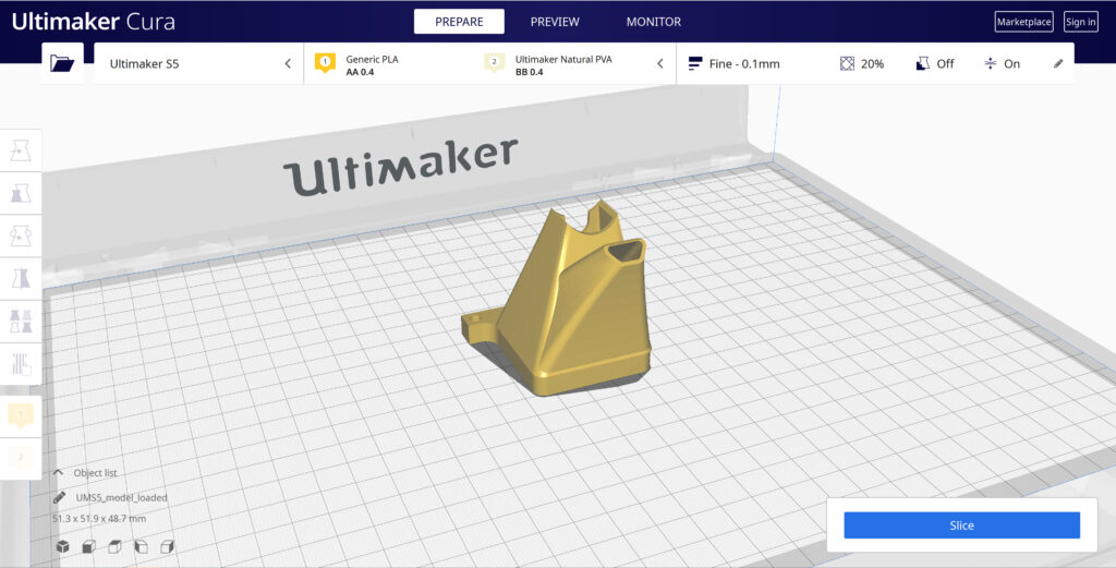
Loading Model and Print Orientation
You can load your print model in one of three ways:
In the top left corner, go to File > Open File(s) > Select Model File.
In the top left, you will see an “Open File” icon.
You can drag and drop your model file onto the build platform representation.
After your model has been loaded onto the platform, you will want to consider how to position it for ideal printing. In general, you will want a flat surface on the build plate to help with adhesion whenever possible.
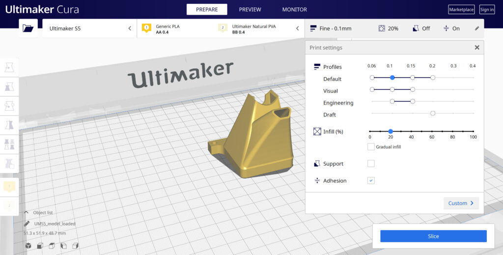
Quick Profile Options
When first starting with your 3D printing journey, you will want to remain within the recommended settings as provided within Cura. These settings will help ensure reliability and quality for the vast majority of models you will print.
The Profiles section will allow you to set layer height based upon different factors such as visual look, engineering quality, or draft settings.
The Infill (%) section will allow you to determine how solid your model file is. 10-20% is perfectly fine for most non-load-bearing components.
Gradual Infill option will print your object with less infill lower down in the model and increase as the object prints to help support the upper skin of the print.
Support generates support structures to help your object print overhangs and steep angles. A general rule of thumb is your printer will not require supports if your model is between 45 and 90 degrees of the build plate.
Adhesion is turned on by default for most profiles and helps secure your object to the build plate. It does this by increasing your objects footprint, by printing lines around the base of your object.
Generate and Print Your File
After you have your model positioned and changed any settings you desire for your application, it is time to generate the print file and get it to your printer. The process of generating your machine directions is called “slicing” as it cuts your model into slices to generate the code.
Slicing Your Model File
Automatic Slicing can be enabled through Preferences > Configure Cura > Enable Automatic Slicing. When enabled, Cura will automatically begin to slice your model after each setting change. This can be an intensive load on your computer and is recommended to disable this for older computers.
When “Enable Automatic Slicing” is disabled, Cura will wait to generate your file until you select “Slice” from the lower right-hand corner.
Printing Your File
Ultimaker provides a direct printing option via USB or allows you to send your print file over the network.
Printing via USB will require you to save your print file to the piece of hardware, and manually insert it into your printer. Once inserted, you will be able to select and start your print file from the user interface on your printer.
Printing over network requires you to sign into your Cura connect account, and you can then send the print file directly to your machine. This can then be started through the user interface on the panel or through Cura connect interface within Cura.
Before you can start printing on the Ultimaker S3/S5, you need to load materials into the printer. For the first use, it is recommended to use the spools of Tough PLA and PVA that come with the Ultimaker S3/S5.
Load Material 2
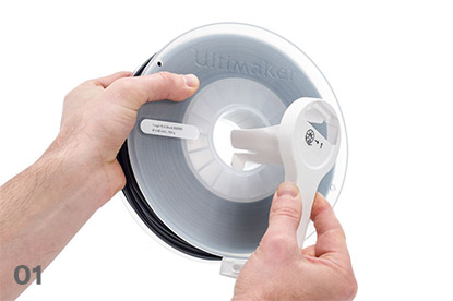
01
Place the spool with material 2 (PVA) onto the spool holder and select Confirm. Make sure the end of the material points in a clockwise direction, so that the material can enter feeder 2 from the bottom
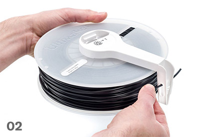
02
Wait until the Ultimaker S5 detects the material and Confirm
03
Insert the end of the material into feeder 2 and gently push it until the feeder grips it and the material is visible in the Bowden tube. Select Confirm to continue
04
Wait for the Ultimaker S5 to heat up print core 2 and load the material into the print head
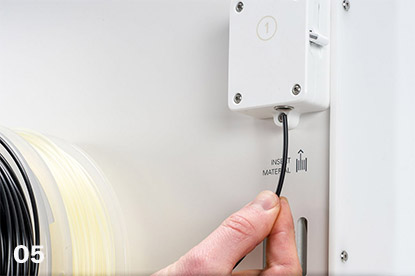
05
Confirm when the new material extrudes consistently from print core 2
06
Wait a moment for print core 2 to cool down
Mount material spool for extruder 2 firstInsert material into feeder 2
Load Material 1
Material 1 will be put on the material guide first before placing it on the spool holder in order to avoid any tangling of the 2 materials during printing. Select material 1 from the list on the touchscreen, select Start, and follow the steps below.
01
Take the material guide and hold it with the outer part towards you
02
Place the material spool with material 1 (Tough PLA) on the material guide with the material in a counter-clockwise direction, and guide the end of the material through the hole in the material guide
03
Place the material guide with material 1 on it onto the spool holder behind material 2, and select Confirm
04
Wait until the Ultimaker S5 detects the material and select Confirm
05
Insert the end of the material into feeder 1 and gently push it until the feeder grips it and the material is visible in the Bowden tube. Select Confirm to continue
06
Wait for the Ultimaker S5 to heat up print core 1 and to load the material into the print head
07
Confirm when the new material extrudes consistently from print core 1
08
Wait a moment for print core 1 to cool down
Prepare the reel for installationRoute the filament through the guideMount the filament reelGuide filament into the feeder
Carefully place the Ultimaker S5 on top of the Material Station
02
Insert a tube coupling collet in the bottom of each feeder of the Ultimaker S5
03
Insert the left Bowden tube of the Material Station into the left feeder, and the right Bowden tube into the right feeder
04
Secure the Bowden tubes with clamp clips
05
Place the spool holder cap into the hole of the Ultimaker S5’s spool holder
Air Manager Installation
Mount the Air Manager on the Ultimaker S5
01
Align the mounting bracket with the back of the Ultimaker S5
02
Guide the Bowden tubes and print head cable into both mounting bracket slots. Above feeder 2, make sure that the Bowden tube is placed in front of the print head cable
03
Gently push down on the mounting bracket until it clicks firmly into place
04
Align the bottom of the filter housing with the slots in the mounting bracket and push it into place
05
Gently push the filter completely into the filter housing
06
From the front of the printer, place the cover over the filter housing
07
Align the hinges with the mounting bracket and drop the cover into place
Plugin the connectors
01
Connect the Air Manager cable to the port at the back of the Air Manager
02
mounting bracket around the Air Manager cable and close it
03
Slide the stress relief clip upwards until it cannot go further to secure the cable in place
04
Connect the other side of the Air Manager cable to the UMB OUT port on the Material Station
05
Connect the Material Station cable to the UMB IN port on the Material Station and the other end to the UMB OUT port on the Ultimaker S5
06
Connect the power extension cable to the Ultimaker S5 and the Material Station
07
Connect the power cable to the Material Station and the other end to a power outlet
After your print has completed, it will need to removed from the glass build plate. There are a few separate techniques to accomplish this, and each can have advantages depending on the specific part and whether any additional adhesives were used.
Wait For the Glass Plate to Cool Down
If you printed directly on to the glass plate without using an adhesive, and if the build plate was not leveled too tightly, the print may easily be removed once it is cool. Simply allow the build plate and the print to cool down after printing. The material will contract as it cools and you can easily remove the print from the build plate.
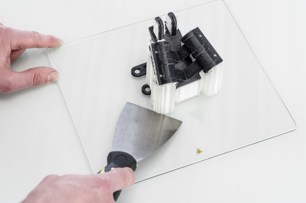
Use a Spatula or Scraper
If your print doesn’t remove from the build plate after cooling, you can use a spatula to remove the print. Place the spatula under the print and apply a small amount of force to remove the print.
NOTE: Take the glass plate out of the printer to avoid damaging the build plate clamps.
Use Water to Remove the Print
If neither of these methods work, remove the print using water. Remove the glass plate and print from the Ultimaker. Be careful not to burn your fingers if the glass plate is still warm. Run cool tap water on the backside of the plate to cool it quicker – the print material will contract more than during a normal cool down. Once the plate has cooled, the print can be popped off.
If glue or Magigoo was used on the glass plate, run lukewarm water over the print side of the plate to dissolve the glue. Once the glue has dissolved, it should be easier to remove the print. If PVA was used, place the glass plate and print in water to dissolve the PVA – this makes print removal easier.
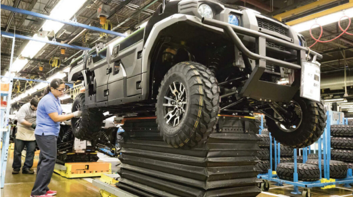
Implementing Solutions On Current Manufacturing Lines
The team at Nissan has gone above and beyond by using 3D printed tools, jigs, and fixtures to remold their workflow, resulting in remarkable time and cost savings. This case study highlights over twenty separate applications that Nissan has been able to implement throughout their assembly line. Download now to learn more about:
Needs in a manufacturing environment can be varied and difficult to plan for logistically. Metro Plastics, an injection mold manufacturer, has turned their Ultimaker S5 printer into an everyday workhorse, saving them time, money, and manpower in everyday production needs. Explore how they have been able to:
Drastically cut down lead times from their internal tool shop
Generate customized and streamlined parts for easy printing and minimal post-processing
Kawasaki Deploys Large Format BigRep Printers to Increase In-HouseTooling
Discover how Kawasaki used BigRep printers to solve manufacturing issues, reducing their reliance on outsourcing tooling components. Download this white paper to see:
How to save as much as 85% compared to outsourcing manufacturing components
How to replace end tooling equipment with 3D printed components
Leveraging large format printing for custom fixtures
Save Money By Producing Tools, Jigs, and Fixtures In-House
Learn how Volkswagen developed customized solutions to address specific problems, re-engineer the application of concepts applied on an auxiliary system, get rid of paperwork, and shrink implementation time on new tooling. Discover how Volkswagen:
Brought 93% of outsourced tooling in-house
Reduced costs by testing prototypes instead of redesigning existing molds
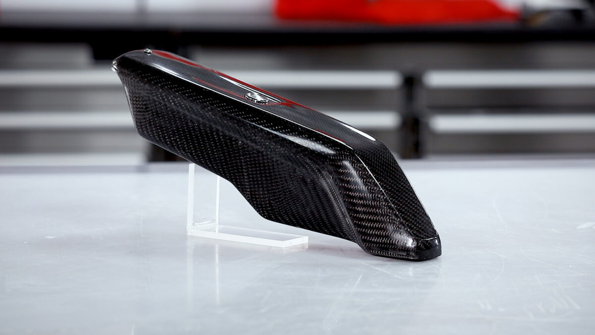
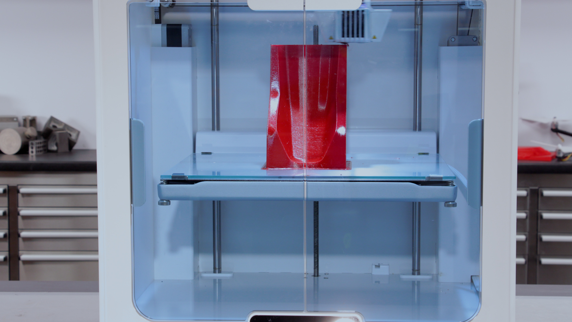
In this tutorial, we skip the process of using a pattern to create a mold and directly create a mold using 3D printing. This tutorial is a bare-bones carbon fiber process meant for those without the specialized equipment needed for more technical processes and high-temperature epoxies.
We will be taking a FFF print with the barriers already modeled and release-coating it before manufacturing the carbon fiber part using a simple hand layup process. Non-cosmetic parts can be used directly from the mold, however, the surface will be slightly compromised by the resolution of the 3D print and limitations of a hand layup process. To bring the finish up to a perfect standard the part can be coated in XCR coating resin and flatted and polished to a high-quality finish.
Material Compatibility
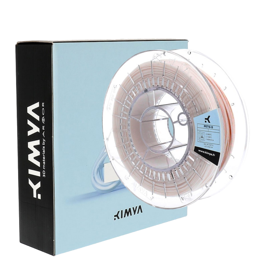
PET-G filament is highly recommended due to its good release properties with the epoxy resin. ABS should be avoided as a direct mold material as you may find if difficult to get a good release from epoxy resin.
After 3D printing, the mold should be prepared with a release agent. The most reliable release agent for this process is PVA release agent, as it helps to smooth out layer-lines while providing a reliable release from the epoxy resin.
The resulting mold from this process will work with most conventional resin systems, such as epoxy polyester and vinylester. Generally molds made in this way are best suited to hand layup processing (with or without a vacuum bag). It would also be possible to process using resin infusion but due to 3D prints generally not being 100% airtight, an envelope bagging method may have to be used. Molds made with this process are not suitable for elevated temperature cures, as used in prepreg production, even when the HDT of the PETG is not theoretically exceeded, we have found the stress of the vacuum bag will lead to excessive warping and distortion.
Materials & Equipment Needed
3D Printed Part – For this tutorial, we use the Ultimaker S5 which is an affordable, end-to-end 3D printer with hundreds of ready-to-print materials.
XC110 210g 2×2 Prepreg Carbon Fiber: We are using three plies in this project but any dry composite reinforcement can be used.
EL2 Laminating Epoxy: Which is specifically designed for wet layup processing and offers excellent strength and wet-out performance. The back of the part is then finished with our Economy Peel-Ply which provides a neat inner surface.
XCR Coating & NW1 Polishing Compound (optional): Use these to post-process your carbon fiber part, providing a better cosmetic finish on your end product.
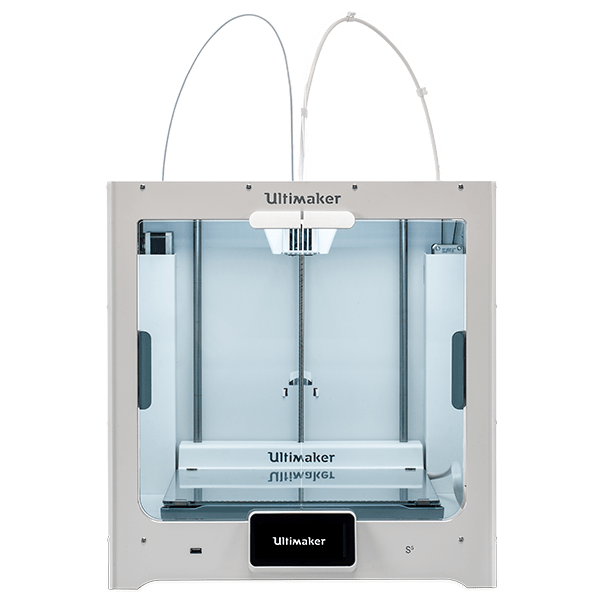
Ultimaker S5
A large, easy-to-use 3D printer with massive, ready-to-print material ecosystem.
Design and 3D print your mold with any flanges or extensions required to aid in the layup. We suggest using PET-G for directly printed molds due to its reliable release properties. Printing at a higher resolution will provide a smoother mold surface that is easier to release from. For this project we printed with ‘standard’ CURA Slicer settings with a 0.15mm layer height. If possible, orient the part so that the layers are printed parallel to the direction of release of the part, this will reduce the mechanical lock presented by the print surface. That being said, as long as you have a draft-angle of 5deg or greater you can still get a good release, even if the layer-lines are perpendicular to the release direction.
For larger molds, BigRep 3D Printers provide build volumes up to 1m3, or your design can be printed in sections and then bonded together with an appropriate adhesive. Although, PET-G may have some bonding issues due to its release properties.
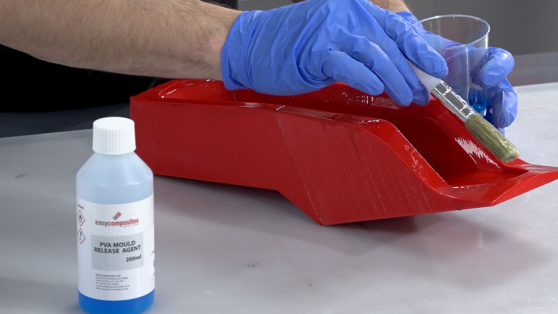
2. Apply the Release Agent
Although PET-G will offer an inherent release with epoxy resins a release agent is still required to ensure that the part will separate from the mold. We recommend PVA release agent, as it offers a very fast and reliable release in this process. PVA is applied in a single coat either by wiping or brushing an even film over the mold surface. This coating should be liberal but not so thick that it causes runs. Once applied, the PVA release agent should be allowed to dry as room temperature, typically this will take around 30 minutes.
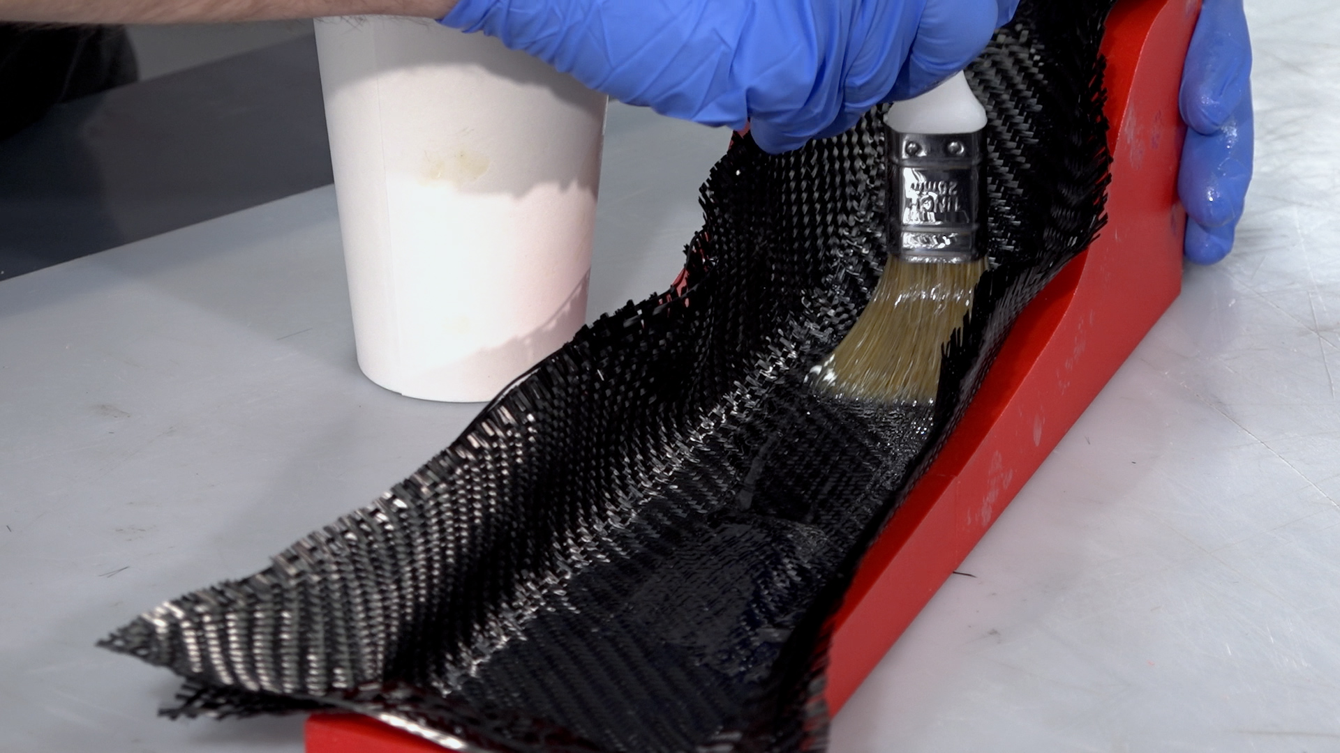
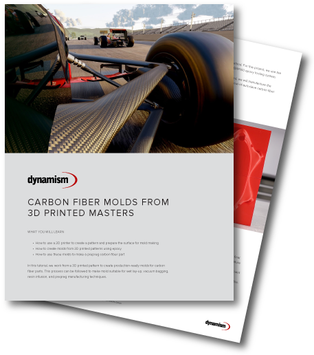
3. Laminate the Part
For this project, we are using the EL2 laminating resin. Be sure to accurately and thoroughly mix the resin with its hardener. It is best practice to pour from the first container into a second and mix again to ensure there is no unmixed resin.
Before laying the carbon, the mold should be coated in a film of resin. When hand laminating you should, wherever possible, lay the carbon onto the resin and wet out the fabric with resin from underneath. This will help to ensure proper wet-out and will reduce air entrapment. For small intricate parts, a laminating brush will be needed but for larger or flatter moldings, a roller or squeegee can aid the wetting out. For a wet lay-up you are typically aiming for a fibre to resin fraction of 1:1 so for every 100g of fibre you will use approximately 100g of resin.
With parts 3mm thick or less, it is usually possible to laminate all of the layers in one single operation. For thicker parts, it may be necessary to divide the layup into multiple laminations to reduce the effects of shrinkage and the possibility of a thermal runaway or ‘exotherm’.
On this project, after the reinforcement is laid, a layer of peel-ply is used as a final ply to create a neat finish on the inside of the part, which also provides a good surface for subsequent bonding operations. With the peel-ply laminated, the part can then be left to cure at ambient temperature. Cure times will vary depending upon the hardener speed and the room temperature but will typically range between 12 and 48hrs.
CAUTION: Do not leave the mixed EL2 resin in the bottom of the mixing cup if deeper than 5mm. This can undergo a thermal runaway which can be potentially dangerous. Excess resin should be poured into a tray to increase the surface area and/or the container should be moved to a safe outdoor location in case of overheating.
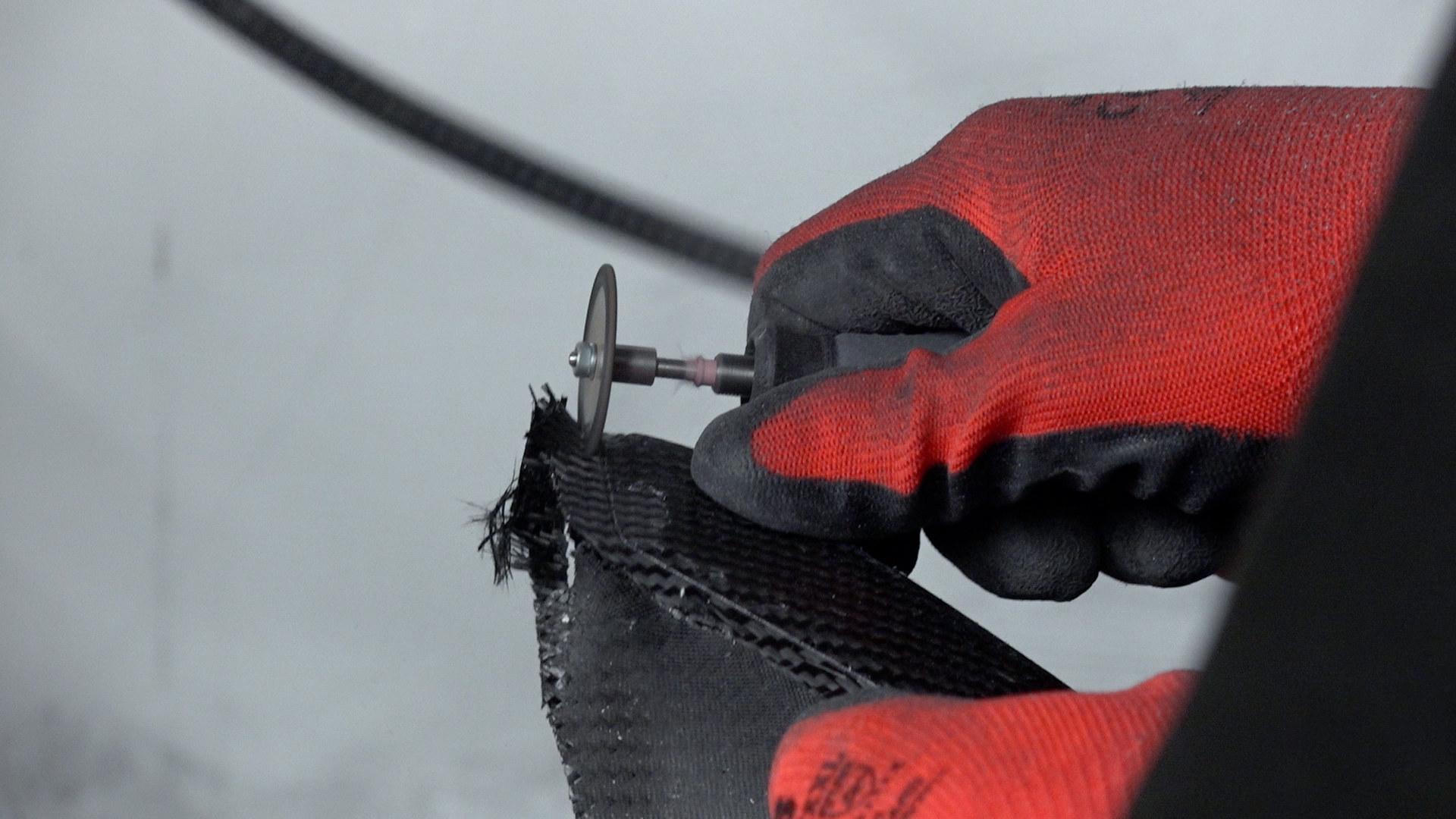
4. Trim
After demolding, trim and finish to give a clean edge to the part. For our project, we used a Dremel type tool fitted with a 32mm Permagrit cut-off wheel which is an excellent all-round trimming tool and lasts for hours of continuous use. The edges were trued up using a sanding block and finished with 240grit paper. If you are happy with the results as left by the XCR coating, the part could be used as is but generally, sanding and polishing the part would be preferred as it will leave a more consistent and professional finish.
Free Tutorial
Download This Carbon Fiber Tutorial
Learn how to create carbon fiber molds faster and cheaper with 3D printing
In order to achieve a good cosmetic finish without pinholes and print layer-lines, the part can be coated with a resin or clear-coat. To prepare the part, the surface will need to be abraded with 400grit wet and dry sandpaper to provide a good key for the coating.
If your part has any voids or large pinholes, use resin to fill them. For larger voids, a dam created from flash release tape can help to hold the resin back from running out, then use either the EL2 laminating resin or the XCR coating resin to fill it. After the repairs have been made, they should be left to cure and then sanded back in flat with 400grit paper to level with the surface of the part.
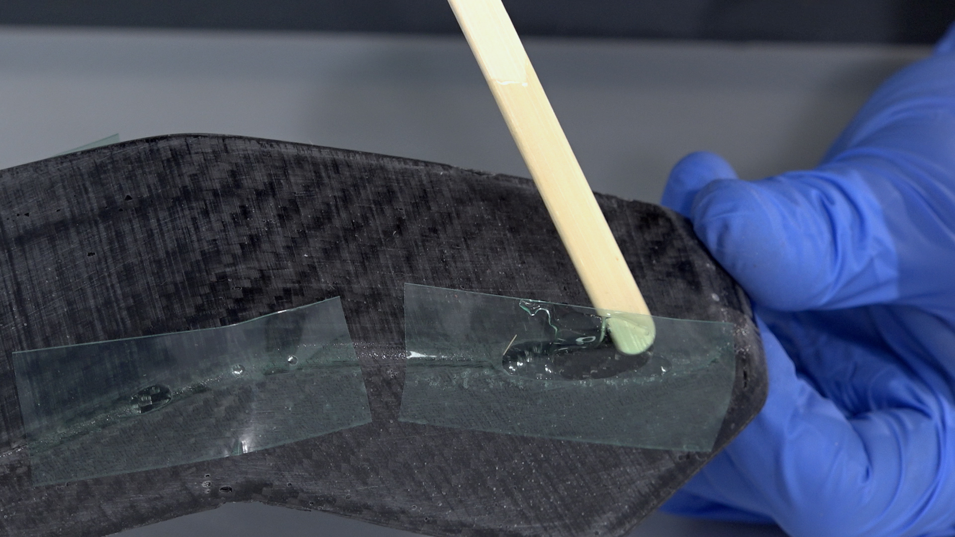
6. Coat with XCR Coating Resin
With the part fixed and sanded, it can now be coated to provide a smooth glossy and durable finish. It is possible to use a clear-coat automotive spray but for this but in this project, we are using the XCR coating resin which will provide a very durable finish and can easily be applied with a brush.
Coat your part in XCR epoxy coating resin—typically around 300 grams per square meter for each coat. Plan on mixing more than is needed to allow for wastage in mixing cups, brushes, etc. The hardener should be added to the resin in the exact ratio of 100:35, as accurately as possible for small batches of resin scales (within one-tenth of a gram accuracy will help). Mix the resin in one cup, then transfer to a second cup and mix again to ensure that there is no unmixed resin trapped.
Use a brush to apply a thin, even coat over the surface. Do not overload the surface as this will lead to runs in the coating. After applying the coat, check a few minutes later for any runs, removing any excess resin a brush.
Depending upon the finish left by the first coat, as second may be required if any of the surface irregularity has not been covered. The second coat should be applied when the first has reached the B-stage. You can identify the B-stage by touching your print with a gloved finger, it should be tacky but leave no residue, typically around three hours for the XCR, but may vary depending upon room temperature. After your second application the resin should be left to fully cure, about 12–24 hours depending upon temperature.
CAUTION: Do not leave the mixed XCR resin in the bottom of the mixing cup if deeper that 5mm. This can undergo a thermal runaway, which will potentially be hazardous. Excess resin should be poured into a tray to increase the surface area and/or the container should be moved to a safe outdoor location in case of overheating.
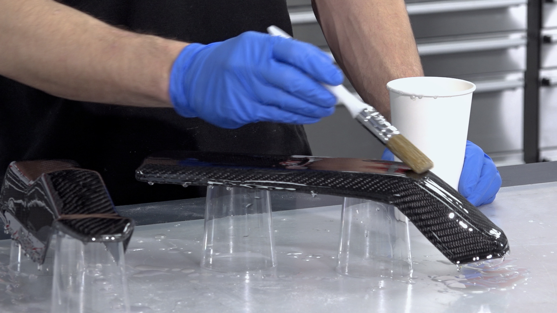
7. Sand & Polish
If you are happy with the results as left by the XCR coating, the part could be used as is but generally, sanding and polishing the part would be preferred as it will leave a more consistent and professional finish.
The sanding process should start with the finest grade of paper that can be used to quickly flatten down the surface—generally either 400 or 800 grit wet and dry. This is best done wet to prevent the paper from clogging, and the grades should be worked through to a minimum of 1200 grit. Use a sanding block for flat areas and single curvatures to maintain an even, flat face and the paper along can be used for the remaining curved areas. Whenever changing to a finer grade of abrasive, clean the pattern and change the water to prevent scratches from particles of the previous grade.
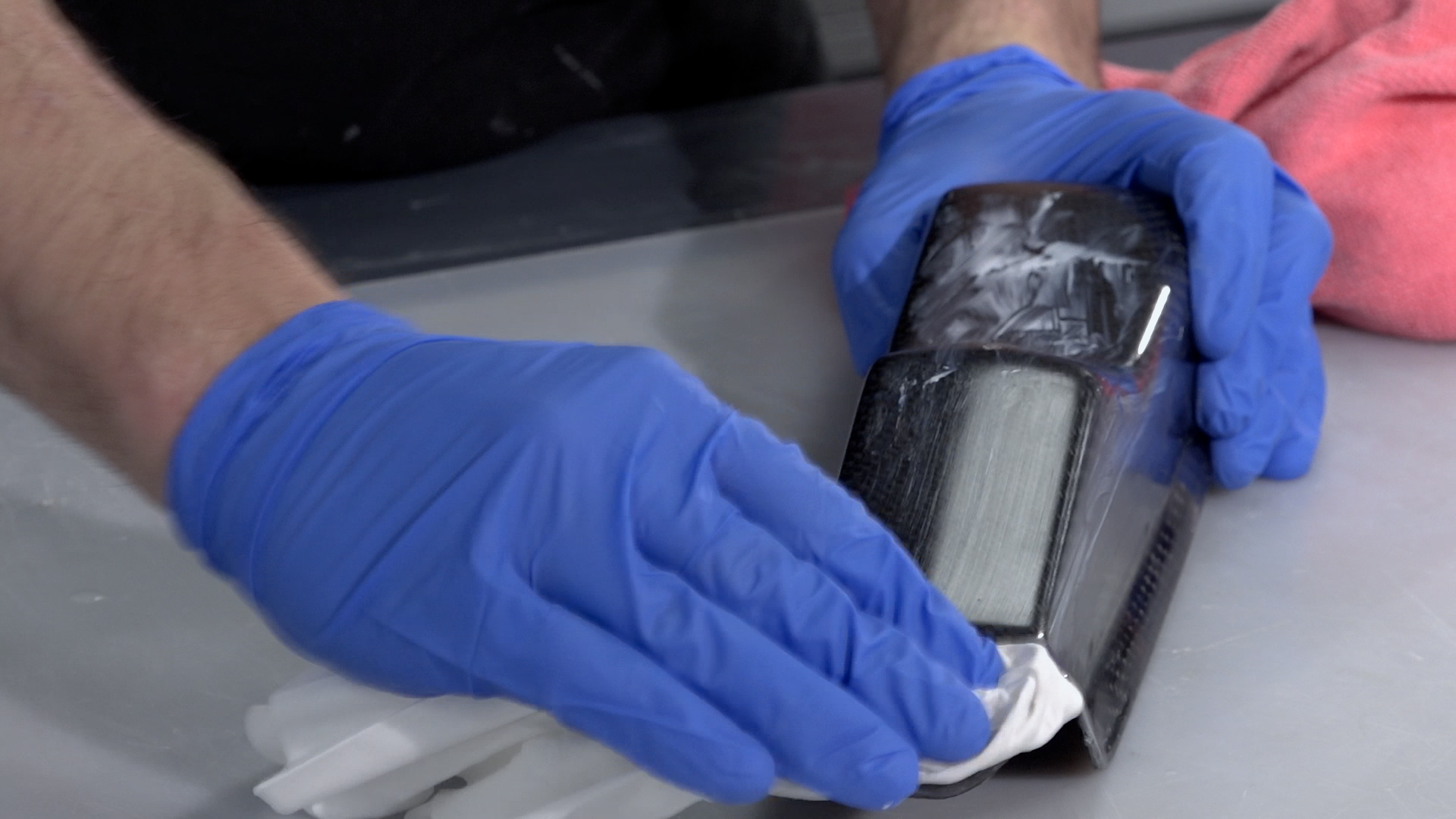
After the 1200 grit (or finer), continue with the final polish using the NW1 polishing compound. Unless your part is very small, this is best done with a foam pad on a polishing machine.
Unlike many compounds, the NW1 does not need water and does not quickly dry out. This particular compound is self-diminishing—the more you work it, the finer it gets. You should be able to achieve a full mirror polish in one step. Once buffed, the last residue of the compound can be wiped away with a microfiber cloth, which should reveal a mirror-like polish on your finished pattern.
Choosing the right 3D printer doesn’t have to be difficult. Find the perfect printer for your application. This in-depth guide covers pricing, materials, dimensional accuracy, and more.