Needs in a manufacturing environment can be varied and difficult to plan for logistically. Metro Plastics, an injection mold manufacturer, has turned their Ultimaker S5 printer into an everyday workhorse, saving them time, money, and manpower in everyday production needs. Explore how they have been able to:
Drastically cut down lead times from their internal tool shop
Generate customized and streamlined parts for easy printing and minimal post-processing
Additive manufacturing dramatically simplifies the process of creating tooling and fixturing. This white paper will cover multiple examples of how Bound Metal Deposition reduces time and cost in manufacturing situations. Discover how:
To generate higher throughput with existing machinery
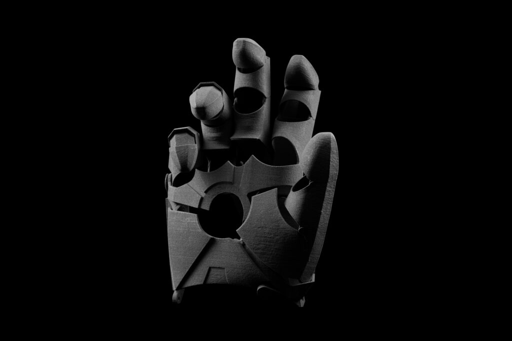
Partial Hand Solutions have been creating custom prostheses since 2007. They have explored a variety of manufacturing methods, and recently started production using a Formlabs Fuse 1 SLS system. Discover how this advanced technology allowed them to:
Deliver truly patient-specific outcomes
Increase accuracy and durability of custom prosthetics
Reduce cost and turnaround time in the manufacturing process
Produce fully moving designs without post-assembly
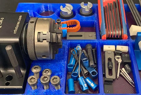
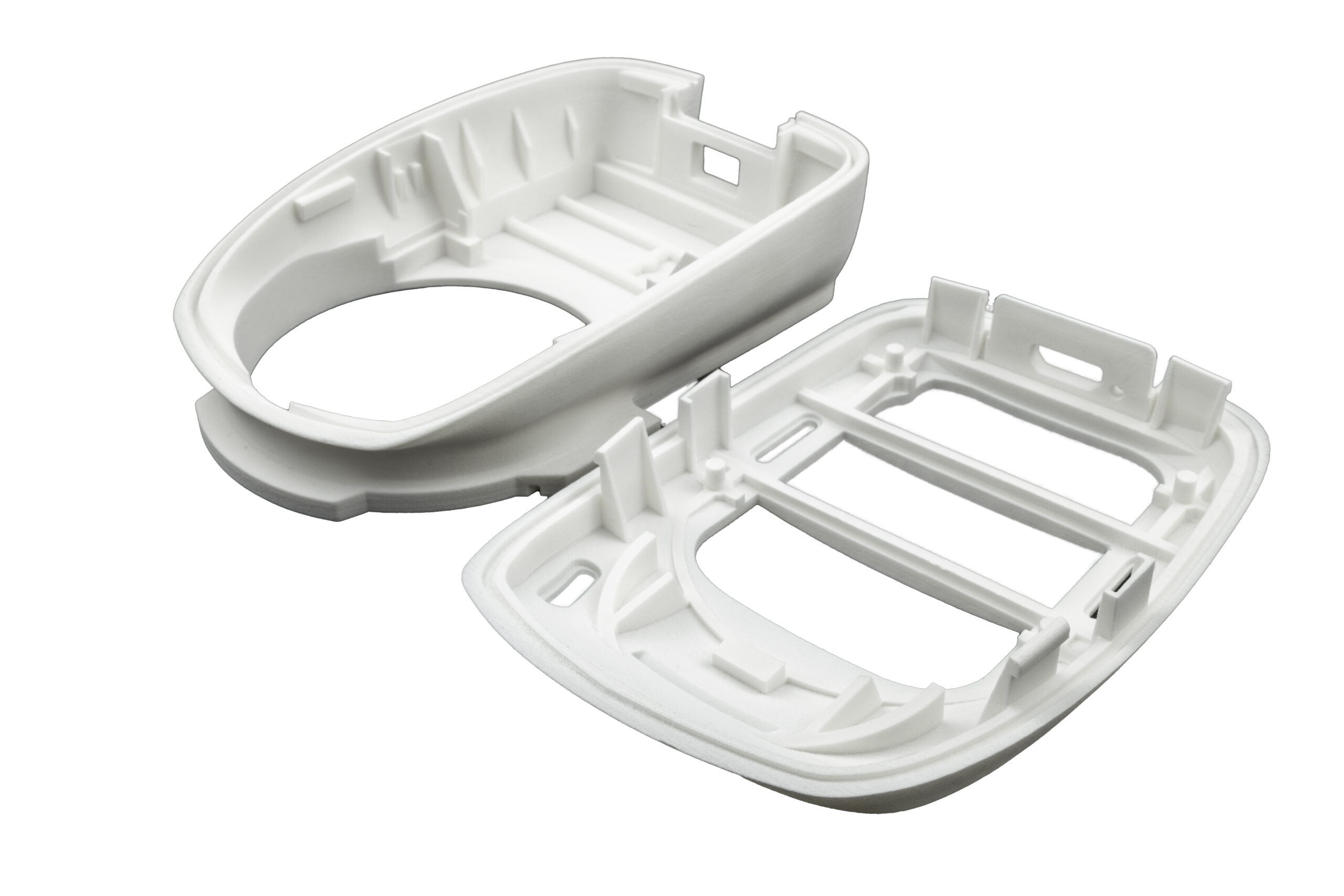
Speed up development with custom tooling and functional end-use parts.Discover how Tessy Plastics has used their Fuse 1 to produce end-use tooling and components, ensuring production deadlines are met while keeping costs low.
On-demand replacement components keep production equipment running
Strong and functional end-use Nylon 12 and Nylon 11 parts open up a wide range of possible applications
Reduce costs, lead time, and storage compared to traditionally tooled parts
3D scanners are useful tools for professionals in a number of applications, including reverse engineering, ensuring part fit within existing designs, inspections, digitizing historical artifacts, and scanning of faces for dental and orthodontic applications.
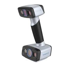
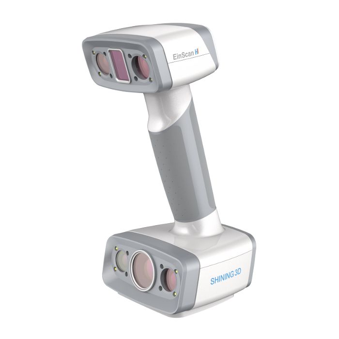
In this guide you will learn the 3D scanning process from start to finish using Shining3D’s new handheld EinScan HX 3D scanner.
The EinScan HX Reverse Engineering Design Bundle provides hybrid blue laser and LED light scanning, providing a solution for surfaces that are difficult to scan with traditional white LED technology.
The EinScan H provides hybrid infrared and LED light scanning for scanning hair (normally not possible with previous scanning technology) and a wider range of object size compatibility.
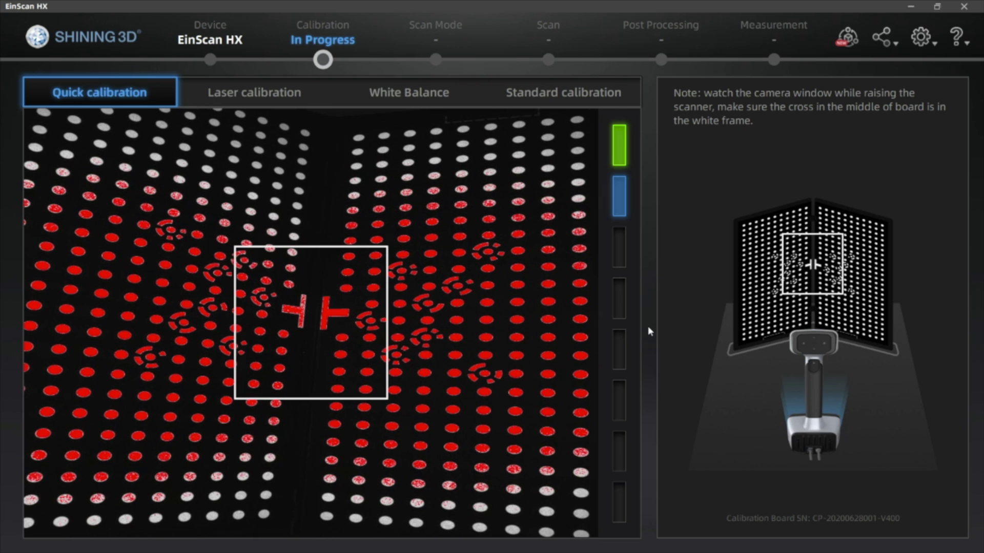
The EinScan scanners require calibration before their first use, as well as after each software update. If calibration is necessary, use your included calibration board and follow the calibration directions as outlined in the software.
2. Model Preparation
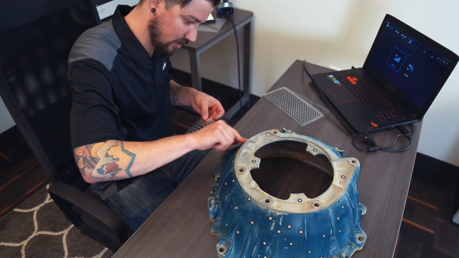
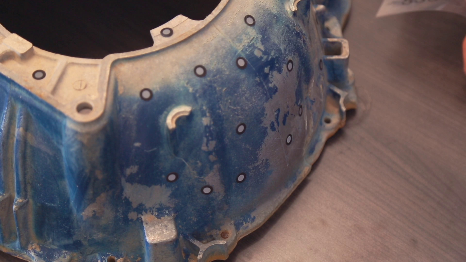
The HX has two scan modes, Rapid Scan and Laser Scan. Rapid scan will need minimal model preparation and will work for most parts, while the laser mode will be best for more accurate results and/or models with darker or shinier surfaces. To begin, we are going to place targets on the model. These targets are used when parts have minimal features or large smooth faces that lack features for the scanner to align itself to. Parts with repetitive features or patterns may confuse the scanner and will require targets placed randomly to help alignment.
To place the targets, all you’ll need to do is place them 2-6 inches apart in a random fashion.
A little trick here, you can also place targets on a table or board and place your object on it. The scanner will use these as reference points, achieving the same goal as placing them on the model without covering some of the details on the part.
Next, if your model has any shiny, dark, or translucent features you will need to dull them so that they can scan properly. We’re using the HX which is great for shiny and dark materials, and as a result doesn’t really any additional surface treatment.
There’s a number of products you can use here including baby powder, spray paint, and specialized sprays that disappear after a few minutes. You can find recommendations in the link below. To coat the part, all you’ll need to do is apply a small film to your model, just enough to dull the surface and that’s it!
2. Scanning
For best results, avoid very bright rooms or having the scanner directly facing a light source.
Start by clicking the play button to begin previewing and adjust brightness based on your environment.
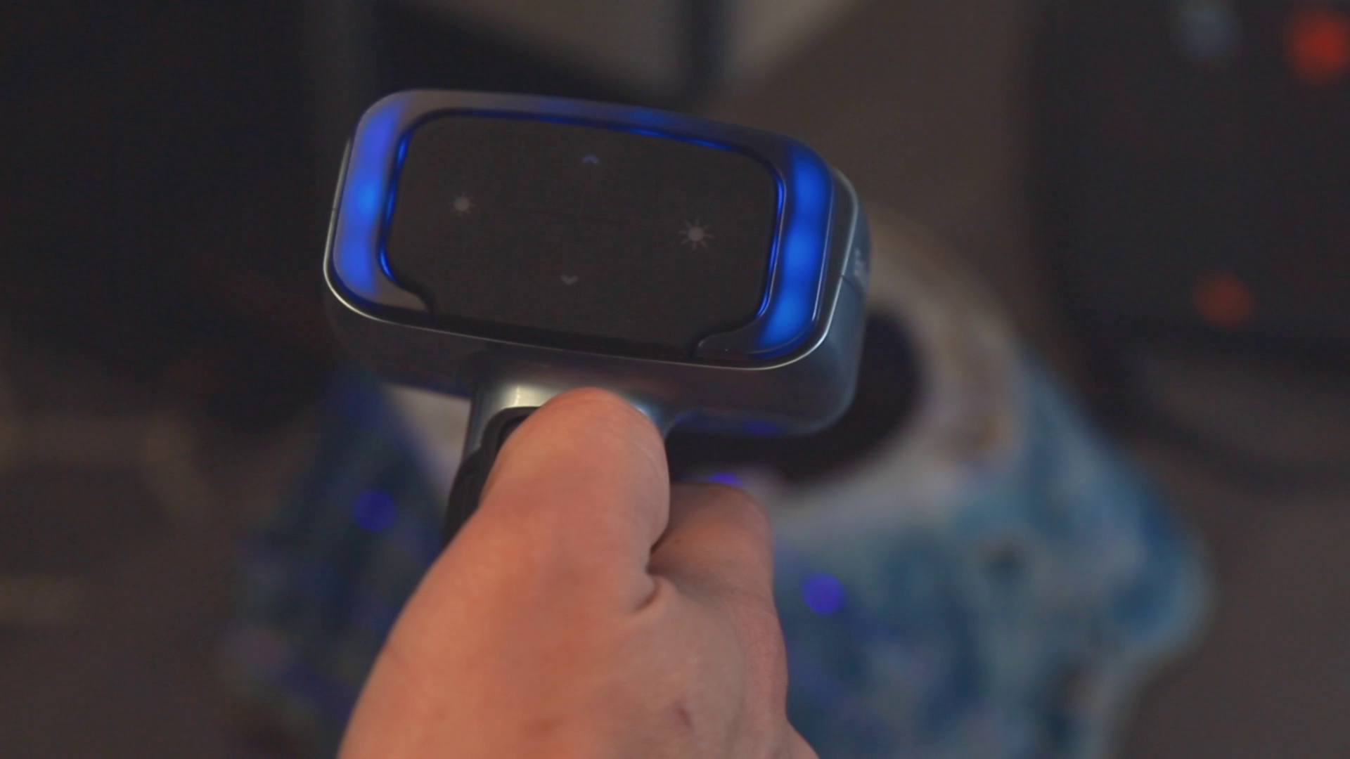
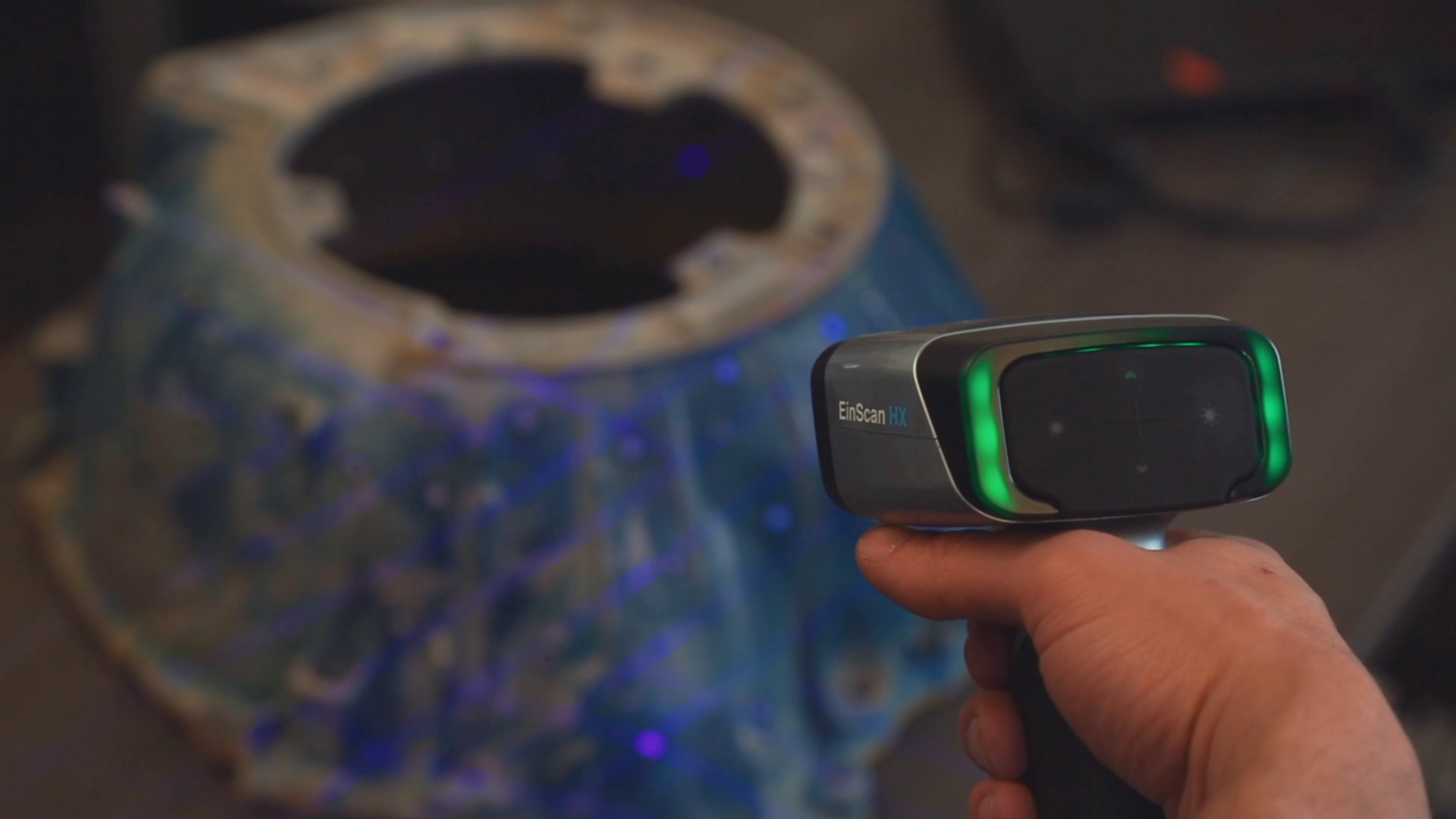
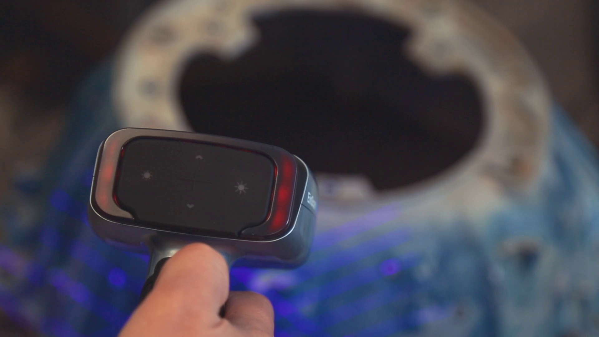
Use the indicator lights to maintain an optimal scanning distance. When you’re at the ideal distance, the indicator on the back of the scanner and in the software will both be green. If you go too far, the light and software will be blue and the software will make a noise. If you get too close, the indicator lights will turn red, also signaled by a noise.
The blue light indicates you’re too far away from the object for proper scanning.
Green is good! You’re right in the sweet spot regarding distance.
The red light indicates you’re too close to accurately scan the object.
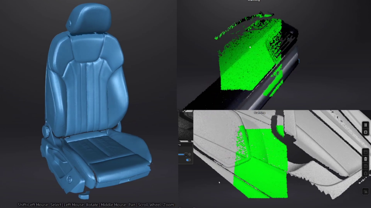
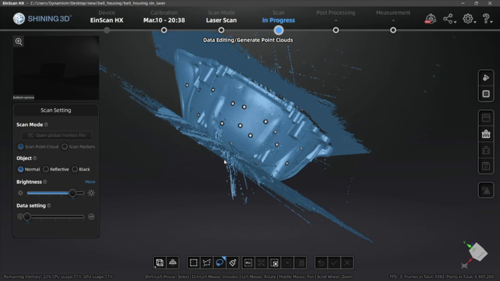
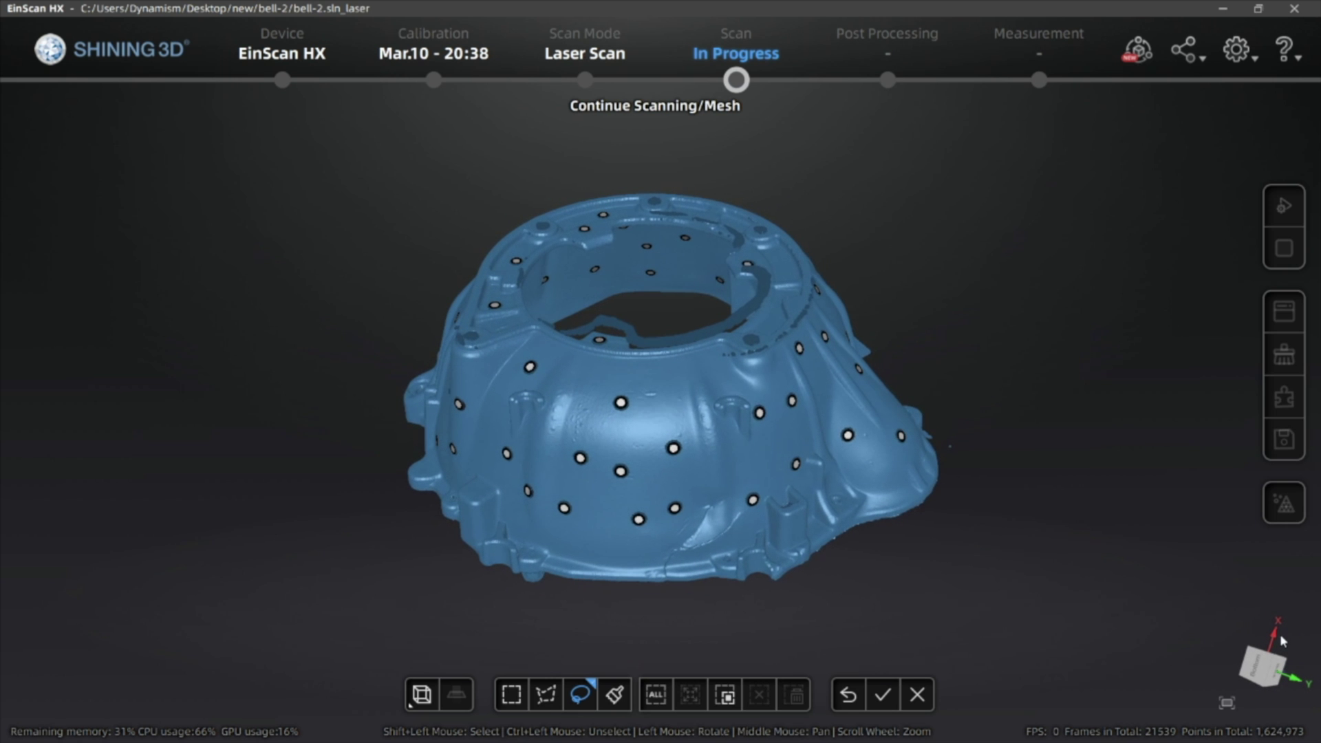
Now, click the play button again to begin scanning. Move the scanner around the object, rotating to help capture different angles. If you need to turn the object, pause the scanner and move it to a better position before resuming.
Once you have scanned your object and generated the point cloud data, you can then generate the mesh of your 3D scan. If you’re planning on using scan data for reverse engineering or QC you can export a non-watertight mesh, however for 3D printing you’ll need to make sure you get a watertight model for optimal results.
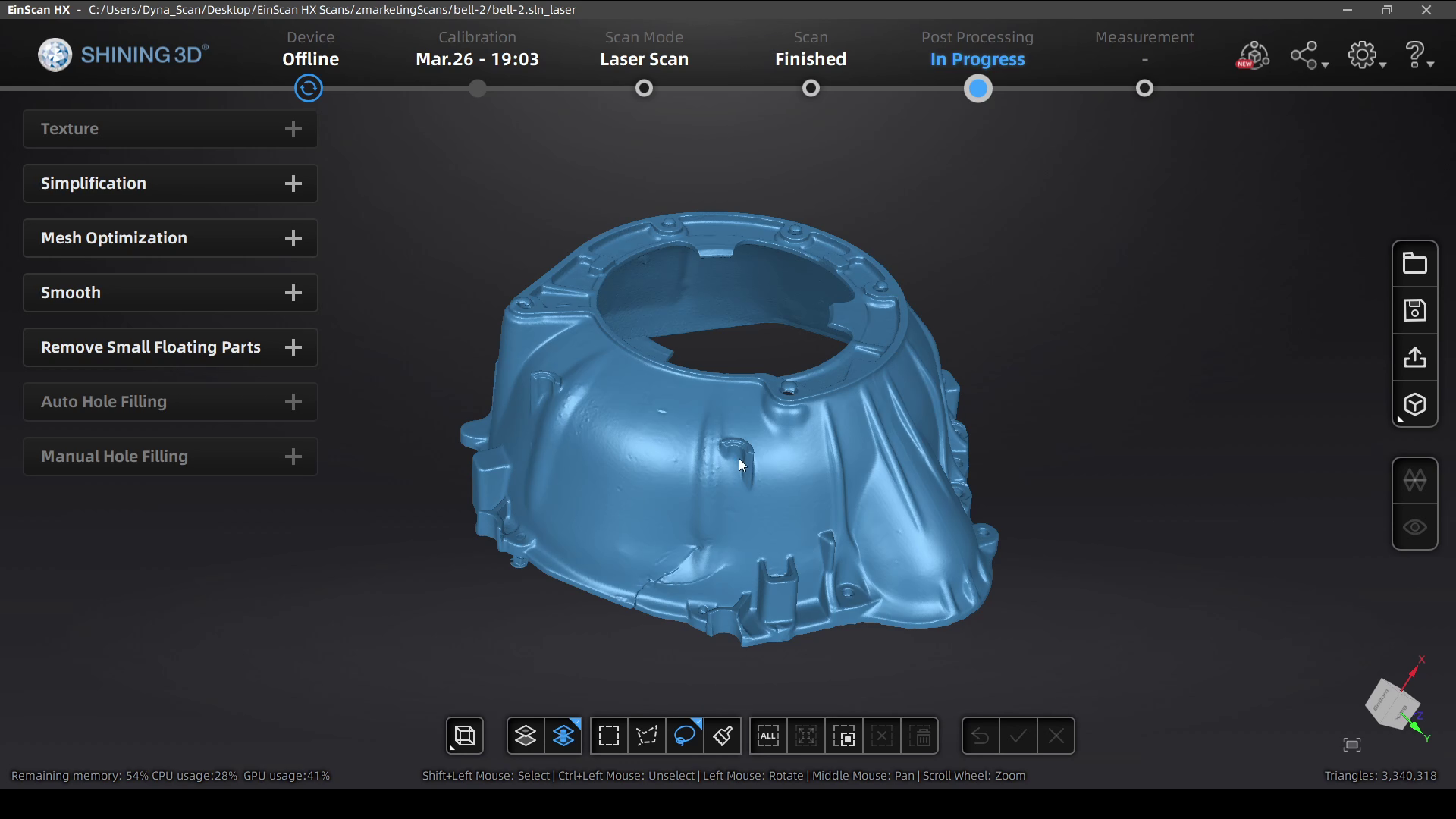
3. Mesh Cleanup
After you get your mesh data, there are a few different tools that available to help get your 3D model ready to be used.
First, you can select and delete data that you don’t need (much like in the other steps in the scanning process).
If the model is not watertight, or you deleted portions of your watertight model, you can also fill the holes manually by selecting each one, or automatically if there are too many to select individually.
Another useful tool is the ability to simplify the object, which is great for reducing the file size while still keeping most of the part quality. You can usually reduce the file by 40-60% without affecting the surface quality of your scan, and it’ll help a lot when you import this 3D model into another program or share it with others.
After you’re done with your edits, the mesh files can be exported as an STL, OBJ, 3MF, or PLY file for use in your reverse engineering process, measuring/QC workflow, or to send straight to your slicing software to 3D print!
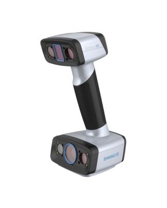
The HX is the best industrial scanner thanks to it’s specialized blue LED rapid scan mode and high accuracy Laser Scan mode leveraging tracking dots for best accuracy.
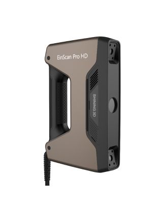
The Pro HD has a special blue LED light which helps at scanning slightly reflective or darker objects. An additional Color Pack camera can be added for full color scanning.
Kawasaki Deploys Large Format BigRep Printers to Increase In-HouseTooling
Discover how Kawasaki used BigRep printers to solve manufacturing issues, reducing their reliance on outsourcing tooling components. Download this white paper to see:
How to save as much as 85% compared to outsourcing manufacturing components
How to replace end tooling equipment with 3D printed components
Leveraging large format printing for custom fixtures
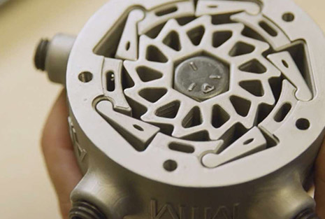
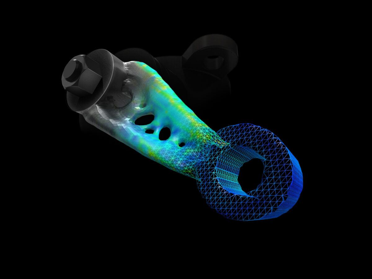
Find out how Solidform, an industry pioneer in the casting prototype business that has manufactured investment and sand castings for the aerospace industry since 1980, was able to reduce an aerospace component’s weight by 65% while maintaining structural integrity. By optimizing this one part, they were able to achieve a fuel cost savings of nearly half a million dollars over the lifetime of an aircraft fleet. In this paper you will learn to:
Optimize parts for reduced weight while maintaining strength requirements
Implement scalable additive manufacturing to meet changing demands
Create castable patterns directly with a 3D printer
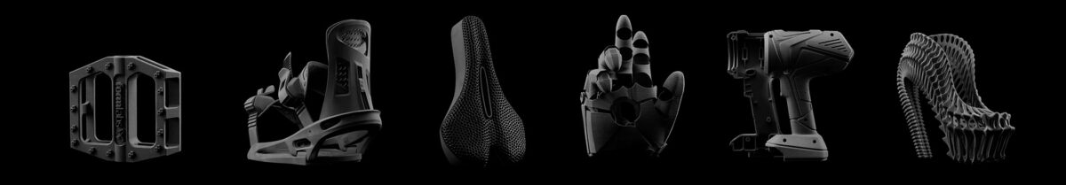
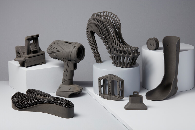
Selective Laser Sintering (SLS) is a 3D printing process that’s currently trusted by engineers and manufacturers across many different industries for its capability in producing strong, functional parts. Due to the ability to densely pack parts within the build volume, as well as the self-supporting nature of the process removing the need for support structures, it’s especially suited for low-volume production. While SLS was traditionally an expensive process with a high initial investment cost, prices have recently dropped significantly, while still delivering quality parts quickly.
However, this approach is not by default suited to all applications. There are significant considerations that must be taken into account when working with powder-based systems, and these can often require additional facilities investment and safety precautions. The variety of available printing materials with SLS may be more limited compared to other 3D printing processes. Parts will also have a textured surface finish that may not be desirable for certain functions
It’s important to fully assess all necessary factors when determining whether or not SLS printing is the right fit for your organization. But this does not need to be a daunting task, and we’re here to help! Download the Guide to SLS 3D Printing for a detailed overview, and don’t hesitate to reach out to our 3D printing experts with any additional questions.
Guide to Selective Laser Sintering (SLS) 3D Printing
Selective Laser Sintering is an Additive Manufacturing (AM) technology that uses a high-power laser to sinter small particles of polymer powder into a solid structure. Grab your white paper now to discover:
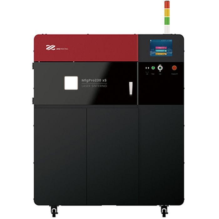
An SLS printer for low-volume production with great material properties that produces isotropic parts. Create engineering quality parts with production capacity to rival injection molding.
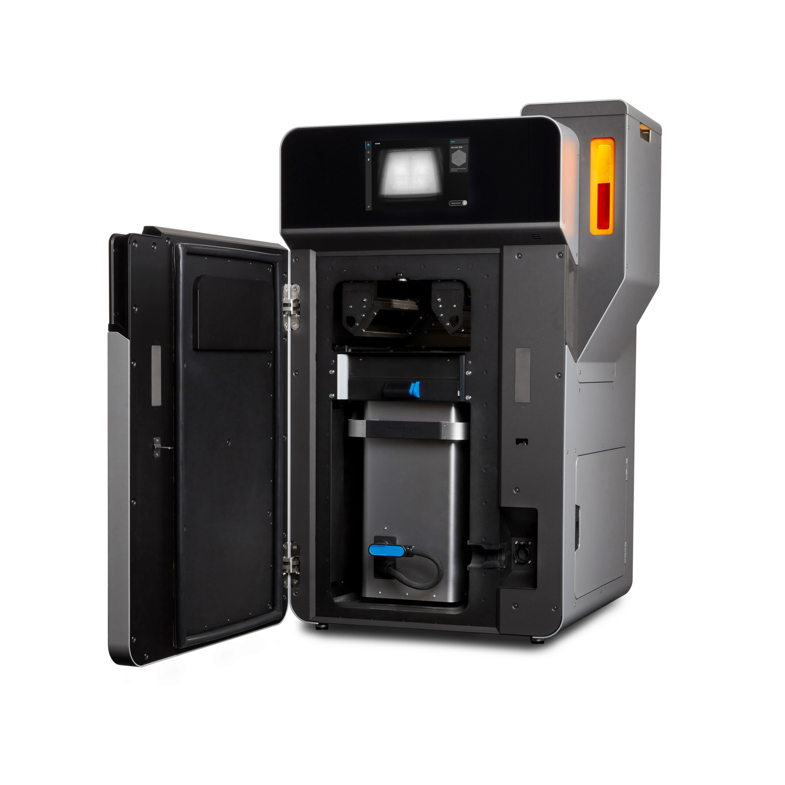
The Fuse 1 and Fuse Sift bring the industrial power of Selective Laser Sintering (SLS) to your benchtop, providing prototyping and production at one tenth of the cost of existing SLS machines.
Want to scale up your production without bringing new hardware in-house? We have the expertise to help! Contact our digital manufacturing team to get your parts made quickly and efficiently.
Save Money By Producing Tools, Jigs, and Fixtures In-House
Learn how Volkswagen developed customized solutions to address specific problems, re-engineer the application of concepts applied on an auxiliary system, get rid of paperwork, and shrink implementation time on new tooling. Discover how Volkswagen:
Brought 93% of outsourced tooling in-house
Reduced costs by testing prototypes instead of redesigning existing molds
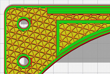
“Teton’s Smart Slice plugin brings engineering grade part simulation to Ultimaker Cura users. Using the integration options of our open and pluggable platform it will make sure parts still meet their engineering criteria, but need less material and therefore saving valuable time and costs. The cooperation with Teton and the integration of their innovative solution are a prime example of how we will be continuously adding value for our professional customers.” Paul Heijmans – Senior VP Software at Ultimaker.
SmartSlice is a plug-in for Ultimaker Cura that empowers users to perform validation and optimization of print parameters based on end-use requirements
Professional and reliable composite-ready 3D printing from Ultimaker, in an efficient and accessible desktop format. Packed with the latest technology, it is as easy to use as it is powerful.