Categories
3D Printing

Slicing A Model File With Cura

General Overview

Cura and other slicing programs transform a CAD model (STL, OBJ, 3MF) into a set of machine instructions that tell your printer how to create your model. There are hundreds of settings that you can control within Cura. Everything from layer height, speed, fan settings, acceleration, jerk etc. Cura comes with pre-made profiles for ease of use and to ensure quality, and it is highly recommended starting with these for all of your prints.

In this support article, we will cover everything you need to know in order to get a print up and running using Ultimakers Cura Software.


Download and Install

Cura is available for Windows, Mac OSX, and Linux operating systems. Ultimaker updates Cura on a regular basis, so be sure to check back for the latest free updates. You can find the most recent version available for download here. After installing the program appropriate for your Operating System, launch the program to prepare your file.


Machine Addition and Selection

After launching the program, you will be prompted to select a machine. In this walkthrough, we will be using the Ultimaker S5. If you are using another Ultimaker product, please ensure to select that machine that corresponds with your product.

Should you ever need to add a new machine for slicing, you can gain access to this same menu by going to the top menu of Cura and going to settings > printer > add printer.


Print cores are compatible with specific material combinations, and it is important to have these properly selected each time you slice a model file.

At the top of the main Cura prepare screen, you will see which current materials and print cores you have selected. Clicking the drop-down arrow on the right hand side will allow you to change the cores as desired.

NOTE: If you have an incompatible material with your print core, a red box will appear and prevent you from slicing your file.


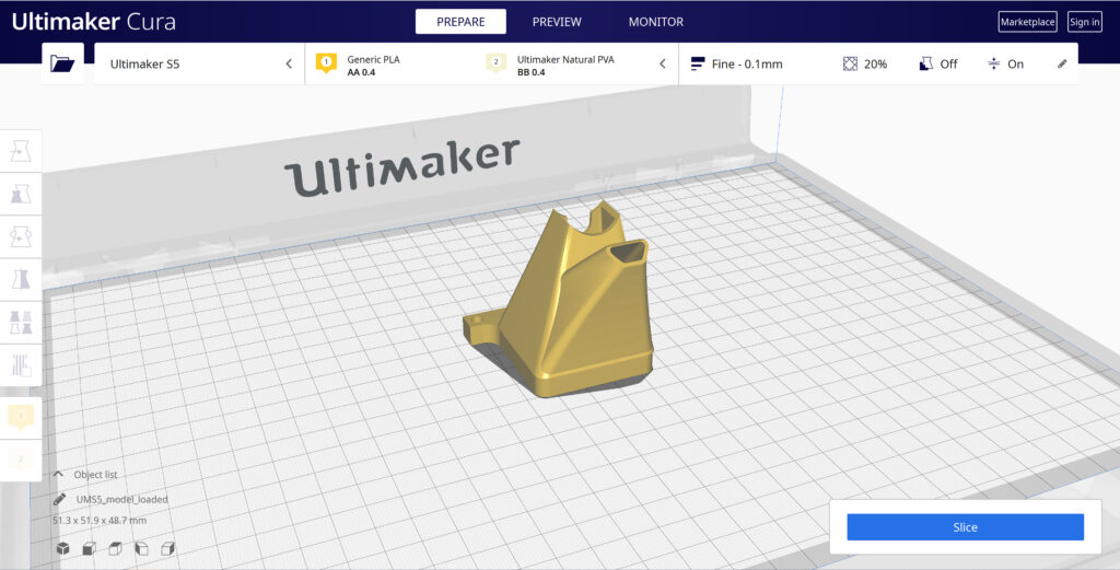
Loading Model and Print Orientation

You can load your print model in one of three ways:

  • In the top left corner, go to File > Open File(s) > Select Model File.
  • In the top left, you will see an “Open File” icon.
  • You can drag and drop your model file onto the build platform representation.

After your model has been loaded onto the platform, you will want to consider how to position it for ideal printing. In general, you will want a flat surface on the build plate to help with adhesion whenever possible.


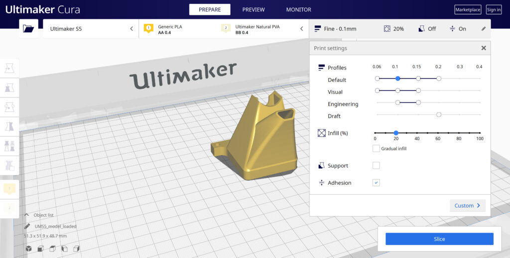
Quick Profile Options

When first starting with your 3D printing journey, you will want to remain within the recommended settings as provided within Cura. These settings will help ensure reliability and quality for the vast majority of models you will print.

  • The Profiles section will allow you to set layer height based upon different factors such as visual look, engineering quality, or draft settings.
  • The Infill (%) section will allow you to determine how solid your model file is. 10-20% is perfectly fine for most non-load-bearing components.
  • Gradual Infill option will print your object with less infill lower down in the model and increase as the object prints to help support the upper skin of the print.
  • Support generates support structures to help your object print overhangs and steep angles. A general rule of thumb is your printer will not require supports if your model is between 45 and 90 degrees of the build plate.
  • Adhesion is turned on by default for most profiles and helps secure your object to the build plate. It does this by increasing your objects footprint, by printing lines around the base of your object.

Generate and Print Your File

After you have your model positioned and changed any settings you desire for your application, it is time to generate the print file and get it to your printer. The process of generating your machine directions is called “slicing” as it cuts your model into slices to generate the code.

Slicing Your Model File

  • Automatic Slicing can be enabled through Preferences > Configure Cura > Enable Automatic Slicing. When enabled, Cura will automatically begin to slice your model after each setting change. This can be an intensive load on your computer and is recommended to disable this for older computers.
  • When “Enable Automatic Slicing” is disabled, Cura will wait to generate your file until you select “Slice” from the lower right-hand corner.

Printing Your File

Ultimaker provides a direct printing option via USB or allows you to send your print file over the network.

  • Printing via USB will require you to save your print file to the piece of hardware, and manually insert it into your printer. Once inserted, you will be able to select and start your print file from the user interface on your printer.
  • Printing over network requires you to sign into your Cura connect account, and you can then send the print file directly to your machine. This can then be started through the user interface on the panel or through Cura connect interface within Cura.
Categories
3D Printing

Loading Filament Into Ultimaker S3/S5

Determine

Before you can start printing on the Ultimaker S3/S5, you need to load materials into the printer. For the first use, it is recommended to use the spools of Tough PLA and PVA that come with the Ultimaker S3/S5.


Load Material 2

01

Place the spool with material 2 (PVA) onto the spool holder and select Confirm. Make sure the end of the material points in a clockwise direction, so that the material can enter feeder 2 from the bottom

02

Wait until the Ultimaker S5 detects the material and Confirm

03

Insert the end of the material into feeder 2 and gently push it until the feeder grips it and the material is visible in the Bowden tube. Select Confirm to continue

04

Wait for the Ultimaker S5 to heat up print core 2 and load the material into the print head

05

Confirm when the new material extrudes consistently from print core 2

06

Wait a moment for print core 2 to cool down

Mount material spool for extruder 2 first
Insert material into feeder 2

Load Material 1

Material 1 will be put on the material guide first before placing it on the spool holder in order to avoid any tangling of the 2 materials during printing. Select material 1 from the list on the touchscreen, select Start, and follow the steps below.

01

Take the material guide and hold it with the outer part towards you

02

Place the material spool with material 1 (Tough PLA) on the material guide with the material in a counter-clockwise direction, and guide the end of the material through the hole in the material guide

03

Place the material guide with material 1 on it onto the spool holder behind material 2, and select Confirm

04

Wait until the Ultimaker S5 detects the material and select Confirm

05

Insert the end of the material into feeder 1 and gently push it until the feeder grips it and the material is visible in the Bowden tube. Select Confirm to continue

06

Wait for the Ultimaker S5 to heat up print core 1 and to load the material into the print head

07

Confirm when the new material extrudes consistently from print core 1

08

Wait a moment for print core 1 to cool down

Prepare the reel for installation

Route the filament through the guide

Mount the filament reel

Guide filament into the feeder
Categories
3D Printing

Material Station and Air Manager Installation

Material Station Installation

Mount the Ultimaker S5 to the Material Station

01

Carefully place the Ultimaker S5 on top of the Material Station

02

Insert a tube coupling collet in the bottom of each feeder of the Ultimaker S5

03

Insert the left Bowden tube of the Material Station into the left feeder, and the right Bowden tube into the right feeder

04

Secure the Bowden tubes with clamp clips

05

Place the spool holder cap into the hole of the Ultimaker S5’s spool holder


Air Manager Installation

Mount the Air Manager on the Ultimaker S5

01

Align the mounting bracket with the back of the Ultimaker S5

02

Guide the Bowden tubes and print head cable into both mounting bracket slots. Above feeder 2, make sure that the Bowden tube is placed in front of the print head cable

03

Gently push down on the mounting bracket until it clicks firmly into place

04

Align the bottom of the filter housing with the slots in the mounting bracket and push it into place

05

Gently push the filter completely into the filter housing

06

From the front of the printer, place the cover over the filter housing

07

Align the hinges with the mounting bracket and drop the cover into place


Plugin the connectors

01

Connect the Air Manager cable to the port at the back of the Air Manager

02

mounting bracket around the Air Manager cable and close it

03

Slide the stress relief clip upwards until it cannot go further to secure the cable in place

04

Connect the other side of the Air Manager cable to the UMB OUT port on the Material Station

05

Connect the Material Station cable to the UMB IN port on the Material Station and the other end to the UMB OUT port on the Ultimaker S5

06

Connect the power extension cable to the Ultimaker S5 and the Material Station

07

Connect the power cable to the Material Station and the other end to a power outlet

Proper cable and PTFE routing
Categories
3D Printing

Removing Prints From Ultimaker

Print Removal Techniques

After your print has completed, it will need to removed from the glass build plate. There are a few separate techniques to accomplish this, and each can have advantages depending on the specific part and whether any additional adhesives were used.


Wait For the Glass Plate to Cool Down

If you printed directly on to the glass plate without using an adhesive, and if the build plate was not leveled too tightly, the print may easily be removed once it is cool. Simply allow the build plate and the print to cool down after printing. The material will contract as it cools and you can easily remove the print from the build plate.


Use a Spatula or Scraper

If your print doesn’t remove from the build plate after cooling, you can use a spatula to remove the print. Place the spatula under the print and apply a small amount of force to remove the print.

NOTE: Take the glass plate out of the printer to avoid damaging the build plate clamps.


Use Water to Remove the Print

If neither of these methods work, remove the print using water. Remove the glass plate and print from the Ultimaker. Be careful not to burn your fingers if the glass plate is still warm. Run cool tap water on the backside of the plate to cool it quicker – the print material will contract more than during a normal cool down. Once the plate has cooled, the print can be popped off.

If glue or Magigoo was used on the glass plate, run lukewarm water over the print side of the plate to dissolve the glue. Once the glue has dissolved, it should be easier to remove the print. If PVA was used, place the glass plate and print in water to dissolve the PVA – this makes print removal easier.

Categories
Automotive Manufacturing

Nissan Utilizes BCN3D To Improve Manufacturing Efficiency

Implementing Solutions On Current Manufacturing Lines

The team at Nissan has gone above and beyond by using 3D printed tools, jigs, and fixtures to remold their workflow, resulting in remarkable time and cost savings. This case study highlights over twenty separate applications that Nissan has been able to implement throughout their assembly line. Download now to learn more about:

  • Improving manufacturing efficiency
  • Robotic automation supplementation
  • Creating custom assembly fixtures
  • Potential for time and cost savings

Categories
Engineering Manufacturing

Machine Design

Custom Machining with Metal Printing

Custom machining methods for prototypes and assemblies can be costly and time-consuming. By utilizing 3D printing to print metal directly, companies have been able to reduce outsourcing costs and tooling backlogs, while opening new possibilities for additional revenue. Review these four use case examples to learn how:

  • Assembly consolidation can can simplify production
  • Additive manufacturing can unlock design elements not possible through other methods
  • Products can be brought to market faster using rapid prototyping
  • More…
Categories
Engineering Manufacturing

Successfully Implementing Additive for Engineering and Manufacturing

14 Manufacturing and Engineering Case Studies

In this collection of case studies, review how companies are currently using Formlabs SLA technology within their workflows. A wide range of applications are covered, including rapid prototyping, production tools, hybrid manufacturing, and end-use parts. Find out how they successfully:

  • Circumvented complex supply chain issues
  • Reduced cost per part by up to 90%
  • Brought prototyping, manufacturing, fixture, and jig production in-house
  • Unlocked mass customization of products
  • And much more…
Categories
Manufacturing

Augmenting Existing Machinery

Reducing Part Weight While Maintaining Strength

When working with automated robotic equipment, ensuring weight and strength requirements are met for all components of the machine is crucial. HARBEC was able to reduce weight while improving strength compared to other additive manufacturing processes. Learn how SLS helped them:

  • Reduce weight of robotic components
  • Improve strength over traditional SLA additive technology
  • Produce wear components in house, saving time and money
Categories
3D Printing

Particle Emissions During 3D Printing

What are Volatile Organic Compounds?

Volatile organic compounds (VOCs) are natural or synthetic airborne chemicals with a vapor pressure above 0.1 kPa at 20 °C. While they are often detectable as smells or odors, scientific detection takes place by sampling air around a printer under controlled conditions and then analyzing the samples. Some VOCs are hazardous. But depending on the molecular structure of the VOC, its safe Threshold Limit Values (TLV) concentration can range from a few micrograms to several milligrams per cubic meter.

Are 3D Printed VOC Emissions Dangerous?

The key to stating whether 3D printing may be harmful to your health depends on safe TLVs. These limit values essentially measure the concentration of ultrafine particles (UFPs) in the air. The fewer particles in the air, the better the health outcome for the user. There are seven key factors to take into consideration when assessing health risks from 3D printing:

  • The room’s dimensional volume affects the TLV. Larger rooms have more air volume and will result in a lower concentration of UFPs.
  • The room’s air exchange rate affects concentration buildup. Faster/more frequent air exchange cycles of the room’s dimensional volume will reduce the UFP concentration.
  • How many 3D printers you are operating. Each printer will generate UFPs, and therefore more printers will produce more UFPs.
  • What material(s) you are printing. Different materials produce different levels of UFPs during normal operation of a printer.
  • How long you are printing. The longer you are printing, the more time UFPs have to accumulate in the room.
  • How close you are to the printer(s). The closer you are to a source of UFPs, the more concentrated they will be.
  • Whether there are other emission sources in the room. Additional emission sources can affect overall room air quality in addition to UFPs from 3D printing.

To dispel any concerns, if you 3D print under the recommended conditions, using any Ultimaker 3D printer and Ultimaker material, there is minimal concern for health risks. For current Ultimaker materials, a nano reference value of 40,000 particles per cubic centimeter (p/cm3) is relevant. Below this concentration, health risks are very unlikely.

This chart provides three average UFP concentration readings for three different print materials. These represent the low, mid, and high end range of possible particulate emissions when using an Ultimaker S5 with the standard configuration that does not include an Air Manager. Specifically, this is due to the level of UFP emission during printing for materials ranging from the low end (PLA) to the high end (Polycarbonate).

Image

* Calculated based on the particle emission rate determined from independent test laboratory measurements and assuming a typical office room of 30.6 m3 with an air exchange rate of 1.8/hr

How Do I Mitigate 3D Printed Emissions?

While it is not possible to eliminate VOC emissions entirely while 3D printing, there are steps you can take to mitigate the particulates released into the local environment.

This chart shows the particulate emissions from the same three materials and printers, along with a second reading taken an Ultimaker Air Manager system has been installed on the printer. For each material, the particle emissions have dropped to less than 500 particles per cubic centimeter. In the case of Ultimaker Polycarbonate, this has reduced overall emissions by more than 95%.

The Air Manager uses a quiet, multi-speed fan to pull air contained inside the enclosed build chamber through a filter, creating an inside-out airflow. This results in nearly all air leaving the printer through the filter, with the exhausted air having the majority of particles removed.

Image

* Calculated based on the particle emission rate determined from independent test laboratory measurements and assuming a typical office room of 30.6 m3 with an air exchange rate of 1.8/hr

Image

Download the Full VOC Emissions Paper

Get the full case study, which details the process used by Ultimaker to determine VOC emissions from their printers and materials.

Final Thoughts

An Air Manager fully encloses the Ultimaker S5 build chamber, providing users with the freedom to set up 3D printers in more locations – including areas where unwanted airflows would negatively impact print quality. Additionally, by providing a physical barrier that stops anyone from touching hot or moving parts, workplace safety is improved. Though it’s up to each individual user to assess the safety of their printing environment and make proper adjustments, adding an Air Manager or filtration solution to your setup mitigates risk substantially, while also improving overall print quality by providing a more consistent print environment.

Image

The Ultimaker 2+ Connect Air Manager (including front door enclosure) fully encloses the build chamber for a more stable printing environment, while preventing anyone from touching hot and moving components during operation.

Image

An integrated filtration solution for the Ultimaker S5 printer, utilizing HEPA filtration while providing optimized airflow settings for all Ultimaker filament. Incorporate safety in your 3D printing workflow.

Image

The 3D PrintPRO extraction system combines high capture performance with proven filter technology, ensuring the effective removal of hazardous particulate, gases/vapors, and odors associated with 3D printing methods. Requires an additional compatible print enclosure for proper operation.

Considering 3D Printing?

Dynamism works with thousands of schools, companies,
and government organizations. We understand the challenges
with acquiring and deploying cutting-edge technology.

Just getting started? Know what you’re looking for? We’re ready
to discuss requirements and help you make an informed decision
about the products you need, all at the best prices available.

Categories
Automotive Manufacturing

3D Printed Injection Molds

Reduce Costs and Leadtimes In Injection Molding

Generating molds for injection molding through traditional methods requires a lot of specialized equipment, time, and money. By leveraging 3D printing and Formlabs Rigid 10k resin, Novus has been able to produce molds at a fraction of the cost and days quicker than outsourcing. This case study will provide an overview of:

  • How to leverage 3D printing in the injection molding workflow
  • How Rigid 10K resin enabled Novus to design faster
  • Best practices for injection molding with 3D printed molds
  • More…